4 layers57.7 × 27 mm
SYZYGY PHY
rustbox/router
Use ARJM11C7-502-KB-EW2 on mouser Tab up, so would have to be placed on the reverse side of the PCB $3.09 @ 10
49 parts
 rustbox/router
Use ARJM11C7-502-KB-EW2 on mouser Tab up, so would have to be placed on the reverse side of the PCB $3.09 @ 10
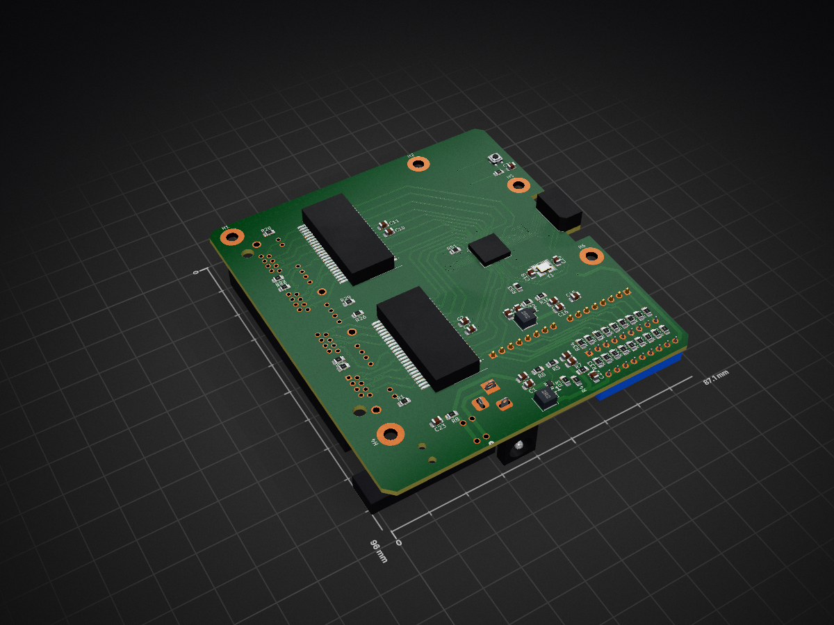
Gsw141-breakout is an open-source printed circuit board by rustbox, from the rustbox/router repository on GitHub. It is a 4-layer board of 87.1 × 96 mm with 119 parts on 171 nets, routed with 1,343 tracks and 60 vias.
It is built around the HSEC8-109-01-L-RA-TR and PB400EEQR1BLK. Its parts include 53 resistors, 45 capacitors, 5 ICs, 5 connectors and 3 switches. It belongs with the interfaces and adapters boards of this library.
Use ARJM11C7-502-KB-EW2 on mouser
4x 1 unit = $12.36
=====================================================================
Use TMJG26945AENL on mouser, 1x2 port
2x 1 unit = $22.68
=====================================================================
Use TMJG46945AENL on mouser, 1x4 port
1149848 4 port RJ45 w/ LEDs, $4.34 each
LAN2VSOD48351C2 dual port magnetics chip, ~$2 each1 @ 4.34 + 2 @ $2 = $8.34
====================================================================
1149854 2 port RJ45 w/LEDs, $2.78 each
LAN2VSOD48351C2 dual port magnetics chip, ~$2 each2 @ 2.78 + 2 @ 2 = $9.56
[ ] How should the 1000 Base T diff pairs be terminated into the magnetics?
[x] 4 port RJ45 jack
[x] RJ45 LEDs
[x] Management Interface
* SPI, etc
* Pin headers
[x] Strapping pins?
* 206-125ST on mouser
* or DS01C-254-L-09BE
[x] GPIO Pins, header
[x] RGMII/SGMII over edge connctor
[x] RGMII/SGMII header
[x] Remove these headers actually
[x] Power regulation, 3.3V, 1.1V
[x] Power jack (latching) and jack
* Mouser T6634ST barrel connector
* 5.5 mm (out) x 2.1 mm (in)
* Out 0v, inside, pos
* Barrel Jack: 694106301002 for above
[x] Clock input
* ECS-400-12-33B2Q-JES-TR3 on mouser
* Clock circuit cap calculation comes from https://blog.adafruit.com/2012/01/24/choosing-the-right-crystal-and-caps-for-your-design/
* CL = C1 * C2 / (C1 + C2) + Cstray
* Cstray is ~3 pF
* If C1 = C2 = C, and CL = 12 pF for the above crystal
* so C = 2(CL - Cstray) => C = 18 pF
[x] Power switch, latching
* Digikey PB400EEQR1BLK maybe?
[x] Reset Button
* button TS21-34-035-BK-160-SMT-TR on mouser
[ ] Power indicator LEDs
[x] GSW Power Startup sequence
* RC delay from 3.3 V into 1.1V enable
[ ] Make sure trace clearance is okay
[ ] Power off?
[x] Power Caps on GSW chip
[x] Blank R for RESREF and RCAL
[ ] Fix the RJ45 / magnetic pinout alignment so routing is easier
[ ] Diff Pairs that are off by more than 10s of mm should be length tuned
[ ] Empty Footprint for linear regulator(s)?
[ ] TI 1G checklist https://www.ti.com/lit/an/snla387/snla387.pdf?ts=1720391456901
| Qty | Value | Footprint | References |
|---|---|---|---|
| 32 | 100n | Capacitor_SMD:C_0805_2012Metric_Pad1.18x1.45mm_HandSolder | C2, C3, C10, C11, C12, C14, C16, C17, C18, C24, C25, C26, C27, C28, C29, C30 +16 |
| 18 | 20k | Resistor_SMD:R_0805_2012Metric_Pad1.20x1.40mm_HandSolder | R33, R34, R35, R36, R37, R38, R39, R40, R41, R42, R43, R44, R45, R46, R47, R48 +2 |
| 16 | 75R | Resistor_SMD:R_0805_2012Metric_Pad1.20x1.40mm_HandSolder | R9, R10, R11, R12, R13, R14, R15, R16, R17, R18, R19, R20, R21, R22, R23, R24 |
| 9 | 100 | Resistor_SMD:R_0805_2012Metric_Pad1.20x1.40mm_HandSolder | R1, R2, R8, R25, R26, R27, R28, R29, R30 |
| 5 | MountingHole_Pad | MountingHole:MountingHole_3.2mm_M3_Pad | H1, H2, H4, H5, H6 |
| 4 | 1000p | Capacitor_SMD:C_0805_2012Metric_Pad1.18x1.45mm_HandSolder | C4, C6, C8, C9 |
| 4 | 47u | Capacitor_SMD:C_0805_2012Metric_Pad1.18x1.45mm_HandSolder | C1, C13, C15, C23 |
| 2 | 100k | Resistor_SMD:R_0805_2012Metric_Pad1.20x1.40mm_HandSolder | R3, R52 |
| 2 | 10k | Resistor_SMD:R_0805_2012Metric_Pad1.20x1.40mm_HandSolder | R7, R32 |
| 2 | 18p | Capacitor_SMD:C_0805_2012Metric | C19, C20 |
| 2 | 2.2uH | Inductor_SMD:L_Abracon_ASPI-0425 | L1, L2 |
| 2 | Conn_01x08 | Connector_PinHeader_2.54mm:PinHeader_1x08_P2.54mm_Vertical | J6, J7 |
| 2 | TBD | Resistor_SMD:R_0805_2012Metric_Pad1.20x1.40mm_HandSolder | R51, R53 |
| 2 | ~ | router:SMD-48 | U2, U3 |
| 1 | 100n | Capacitor_SMD:C_0805_2012Metric | C21 |
| 1 | 10u | Capacitor_SMD:C_0805_2012Metric_Pad1.18x1.45mm_HandSolder | C22 |
| 1 | 1149848 | local:1149848 | J1 |
| 1 | 135k | Resistor_SMD:R_0805_2012Metric_Pad1.20x1.40mm_HandSolder | R5 |
| 1 | 16k | Resistor_SMD:R_0805_2012Metric_Pad1.20x1.40mm_HandSolder | R31 |
| 1 | 22u | Capacitor_SMD:C_0805_2012Metric_Pad1.18x1.45mm_HandSolder | C5 |
| 1 | 30k | Resistor_SMD:R_0805_2012Metric_Pad1.20x1.40mm_HandSolder | R6 |
| 1 | 75k | Resistor_SMD:R_0805_2012Metric_Pad1.20x1.40mm_HandSolder | R4 |
| 1 | Barrel_Jack_Switch | Connector_BarrelJack:BarrelJack_Horizontal | J4 |
| 1 | Crystal_GND24 | Crystal:Crystal_SMD_3225-4Pin_3.2x2.5mm_HandSoldering | Y1 |
| 1 | HSEC8-109-01-L-RA-TR | Connector_Samtec_HSEC8:Samtec_HSEC8-109-X-X-DV_2x09_P0.8mm_Edge | J3 |
| 1 | PB400EEQR1BLK | local:PB400EEQR1BLK_EWI | SW2 |
| 1 | SW_DIP_x09 | Button_Switch_THT:SW_DIP_SPSTx09_Slide_9.78x25.04mm_W7.62mm_P2.54mm | SW1 |
| 1 | TPS563207DRLR | local:SOTFL50P160X60-6N | IC2 |
| 1 | TPS564247DRLR | local:SOTFL50P160X60-6N | IC1 |
| 1 | TS21-34-035-BK-160-SMT-TR | local:TS2134035BK160SMTTR | S1 |
| 1 | ~ | router:XCVR_GSW140A3MC_S_LMHB | U1 |
rustbox/router
Use ARJM11C7-502-KB-EW2 on mouser Tab up, so would have to be placed on the reverse side of the PCB $3.09 @ 10

rustbox/router
Use ARJM11C7-502-KB-EW2 on mouser Tab up, so would have to be placed on the reverse side of the PCB $3.09 @ 10

rustbox/router
Use ARJM11C7-502-KB-EW2 on mouser Tab up, so would have to be placed on the reverse side of the PCB $3.09 @ 10

grantek/minisynth32
A 3D-printable MIDI synthesiser inspired by the Roland MT-32 and clumsyMIDI, and powered by the mt32-pi MT-32 emulator.

petrmikheev/endeavour
Endeavour - open-source FPGA board and SoC ==========================================

Demetrius-Ross/SimMonitor
Rename the main script to main.py '''bash mv espnowsenderrelay.py main.py '''

iandodson/DEN161_GameControllerDesign
Design and full report for a video game controller using an Arduino Micro


Tinkerbug-Robotics/TinkerRocket
Model rocket flight computer, ground station, iOS app, and simulation

It measures 87.1 × 96 mm and has 4 copper layers, 1.6 mm thick.
119 parts, built around the HSEC8-109-01-L-RA-TR and PB400EEQR1BLK. The full list of its parts is on this page, with links to each part's symbol and footprint where PCBKit's library has them.
From the rustbox/router repository on GitHub, at the commit this page was made from: the board is gsw141-breakout/gsw141-breakout.kicad_pcb and its schematic SYZYGY-PHY/SYZYGY-PHY.kicad_sch. PCBKit opens the board in the browser, with nothing to install.
Its repository states no licence, so its author keeps all rights: ask rustbox before reusing the design.