4 layers263 × 179 mm

 rusefi/stim
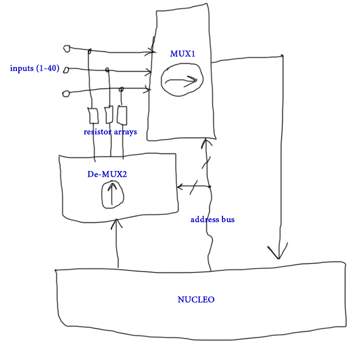
GPIO: output: x4 address pins output: x4 test control pins output: mux off
Digital inputs is an open-source printed circuit board by rusefi, from the rusefi/stim repository on GitHub. It is a 2-layer board of 182.5 × 165 mm with 182 parts on 412 nets, routed with 1,999 tracks and 633 vias.
It is built around the TJA1051T/3/1, TC4427EOA and CD4067BM96, with the ULN2003A, AO3400A and NSMD005 among its other parts. Its parts include 61 resistors, 47 connectors, 18 capacitors, 14 ICs and 9 fuses.


See https://github.com/rusefi/rusefi-hardware/tree/main/digital-inputs for firmware
Part of https://github.com/rusefi/rusefi infrastucture
https://github.com/rusefi/rusefi/wiki/dev-hardware-quality-control
GPIO:
See https://github.com/rusefi/stim/issues/6
| Qty | Value | Footprint | References |
|---|---|---|---|
| 19 | Pad | hellen-one-common:PAD-TH | P1, P2, P3, P4, P5, P6, P10, P11, P12, P13, P14, P15, P16, P17, P18, P19 +3 |
| 14 | 4.7k | Resistor_SMD:R_0603_1608Metric | R4, R6, R8, R10, R14, R15, R16, R17, R18, R19, R20, R21, R57, R60 |
| 12 | 0 | Resistor_SMD:R_Array_Convex_4x0603 | RN1, RN2, RN3, RN4, RN5, RN6, RN7, RN8, RN9, RN10, RN11, RN12 |
| 12 | 100n | Capacitor_SMD:C_0603_1608Metric | C1, C2, C3, C4, C5, C6, C7, C8, C9, C12, C13, C16 |
| 8 | AO3400A | hellen-one-common:SOT-23 | Q1, Q2, Q3, Q4, Q5, Q6, Q7, Q8 |
| 8 | Conn_01x01 | MountingHole:MountingHole_3.2mm_M3_Pad_Via | J10, J11, J12, J13, J14, J15, J16, J17 |
| 8 | nSMD005 | Fuse:Fuse_1206_3216Metric | F2, F3, F4, F5, F6, F7, F8, F9 |
| 7 | 470 | Resistor_SMD:R_0603_1608Metric | R28, R34, R43, R51, R52, R54, R55 |
| 7 | 820 | Resistor_SMD:R_0603_1608Metric | R24, R26, R30, R32, R36, R39, R49 |
| 6 | 100 | Resistor_SMD:R_0603_1608Metric | R25, R29, R44, R46, R47, R59 |
| 6 | CD4067BM96 | Package_SO:SOIC-24W_7.5x15.4mm_P1.27mm | U2, U3, U4, U5, U6, U7 |
| 5 | MountingHole | MountingHole:MountingHole_3.2mm_M3 | H1, H2, H3, H4, H5 |
| 4 | 1.2k | Resistor_SMD:R_1206_3216Metric | R1, R2, R3, R12 |
| 4 | 1.5k | Resistor_SMD:R_0603_1608Metric | R5, R7, R9, R11 |
| 4 | 330 | Resistor_SMD:R_0603_1608Metric | R33, R45, R50, R53 |
| 4 | 47p | Capacitor_SMD:C_0603_1608Metric | C10, C11, C14, C15 |
| 4 | Conn_01x04 | TerminalBlock_Phoenix:TerminalBlock_Phoenix_MKDS-1,5-4-5.08_1x04_P5.08mm_Horizontal | J6, J7, J8, J9 |
| 4 | Conn_02x10_Odd_Even | Connector_PinHeader_2.54mm:PinHeader_2x10_P2.54mm_Vertical | J20, J23, J25, J29 |
| 3 | 220 | Resistor_SMD:R_0603_1608Metric | R31, R35, R42 |
| 3 | 510 | Resistor_SMD:R_0603_1608Metric | R37, R38, R58 |
| 2 | 10k | Resistor_SMD:R_Array_Convex_4x0603 | RN13, RN14 |
| 2 | 10u | Capacitor_SMD:C_0805_2012Metric | C17, C18 |
| 2 | 1k | Resistor_SMD:R_0603_1608Metric | R22, R40 |
| 2 | 2k | Resistor_SMD:R_0603_1608Metric | R23, R41 |
| 2 | DNP | Resistor_SMD:R_0603_1608Metric | R56, R62 |
| 2 | LED-RED-0603 | hellen-one-common:LED-0603 | D3, D4 |
| 2 | OPA2192IDR | Package_SO:SO-8_3.9x4.9mm_P1.27mm | U1, U11 |
| 2 | PESD1CAN | Package_TO_SOT_SMD:SOT-23 | D2, D6 |
| 2 | TC4427 | Package_SO:SOIC-8_3.9x4.9mm_P1.27mm | U8, U9 |
| 2 | TJA1051T-3 | Package_SO:SOIC-8_3.9x4.9mm_P1.27mm | U12, U13 |
| 1 | 1.8A | Fuse:Fuse_1206_3216Metric | F1 |
| 1 | 120 | Resistor_SMD:R_0603_1608Metric | R27 |
| 1 | 13k | Resistor_SMD:R_0603_1608Metric | R13 |
| 1 | 6437288-2 | Connectors:6437288-2 | J1 |
| 1 | 6437288-3 | kicad6-libraries:TE_6437288-3 | J19 |
| 1 | 910 | Resistor_SMD:R_0603_1608Metric | R48 |
| 1 | Barrel_Jack_Switch | Connector_BarrelJack:BarrelJack_GCT_DCJ200-10-A_Horizontal | J2 |
| 1 | CircuitBreaker_1P | lib:RS601HL-1010011BB | CB1 |
| 1 | Conn_01x01 | Connector_Wire:SolderWire-0.75sqmm_1x01_D1.25mm_OD2.3mm | J4 |
| 1 | Conn_01x08 | TerminalBlock_Phoenix:TerminalBlock_Phoenix_MKDS-1,5-8-5.08_1x08_P5.08mm_Horizontal | J3 |
| 1 | Conn_02x04_Odd_Even | Connector_PinHeader_2.54mm:PinHeader_2x04_P2.54mm_Vertical | J28 |
| 1 | Conn_02x06_Odd_Even | Connector_PinHeader_2.54mm:PinHeader_2x06_P2.54mm_Vertical | J26 |
| 1 | Conn_02x08_Odd_Even | Connector_PinHeader_2.54mm:PinHeader_2x08_P2.54mm_Vertical | J21 |
| 1 | Conn_02x14_Odd_Even | Connector_PinHeader_2.54mm:PinHeader_2x16_P2.54mm_Vertical | J30 |
| 1 | Conn_02x15_Odd_Even | Connector_PinHeader_2.54mm:PinHeader_2x15_P2.54mm_Vertical | J22 |
| 1 | Conn_02x16_Odd_Even | Connector_PinHeader_2.54mm:PinHeader_2x16_P2.54mm_Vertical | J27 |
| 1 | Conn_02x17_Odd_Even | Connector_PinHeader_2.54mm:PinHeader_2x17_P2.54mm_Vertical | J24 |
| 1 | LED | LED_SMD:LED_0805_2012Metric | D1 |
| 1 | LM78M05_TO252 | Package_TO_SOT_SMD:TO-252-2 | U14 |
| 1 | ULN2003A | Package_SO:SOIC-16_3.9x9.9mm_P1.27mm | U10 |
It measures 182.5 × 165 mm and has 2 copper layers, 1.6 mm thick.
182 parts, built around the TJA1051T/3/1, TC4427EOA, CD4067BM96 and ULN2003A. The full list of its parts is on this page, with links to each part's symbol and footprint where PCBKit's library has them.
From the rusefi/stim repository on GitHub, at the commit this page was made from: the board is digital_inputs.kicad_pcb and its schematic digital_inputs.kicad_sch. PCBKit opens the board in the browser, with nothing to install.
Its repository states no licence, so its author keeps all rights: ask rusefi before reusing the design.


D0kRay/hpe-mini
Clean Hellen One starter structure for a custom rusEFI-compatible PCB.

OpenLogicEFI/Hardware
Hardware is based off an open source project called Speeduino by Josh Stewart.


