2 layers98 × 27 mm

 runeharlyk/esp-now-controller
A handheld controller built on an ESP32-S3 Super Mini. It reads two two-axis analog joysticks (plus their push-switches), applies per-axis calibration / deadzone / inversion, and broadcasts the normalized state over…
Esp controller pcb is an open-source printed circuit board by runeharlyk, from the runeharlyk/esp-now-controller repository on GitHub, published under the MIT licence. It is a 2-layer board of 160 × 106.2 mm with 5 parts on 10 nets, routed with 99 tracks and 0 vias.
Its parts include 3 ICs, 1 connector and 1 switch. It belongs with the ESP32 boards of this library.
A handheld controller built on an ESP32-S3 Super Mini. It reads two two-axis analog joysticks (plus their push-switches), applies per-axis calibration / deadzone / inversion, and broadcasts the normalized state over ESP-NOW at 50 Hz. No pairing is required - any receiver that adds the broadcast address as an ESP-NOW peer (on the same Wi-Fi channel) will hear it.
Calibration and tuning are configured at runtime through a small text CLI
on the native USB port. The Svelte web app in app/ drives that CLI
over the Web Serial API and visualizes the joysticks live - see
App.
Planned later: OLED status screen (SSD1306), MPU6050 IMU, and a magnetometer. The wire format in
include/controller_packet.his versioned so it can grow without breaking receivers.
The board is 3D printed rather than etched or ordered from a fab. The copper pattern is embossed into the print as ridges standing 0.6 mm proud of a 1.6 mm plate. Copper tape is applied over it, scored along each ridge with a craft knife, and the surrounding foil is peeled away. Components are then soldered directly to the remaining tape. Traces are 1.5 mm and 2.0 mm wide and there are no vias, which is what makes the pattern cuttable by hand.
| Front | Back | Side |
|---|---|---|
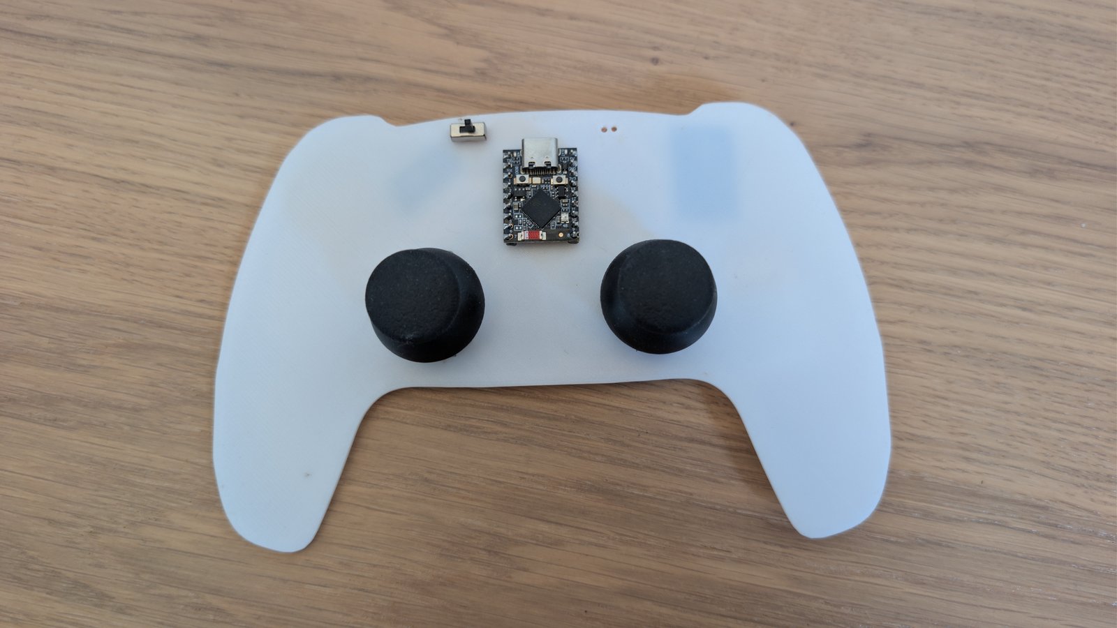 | 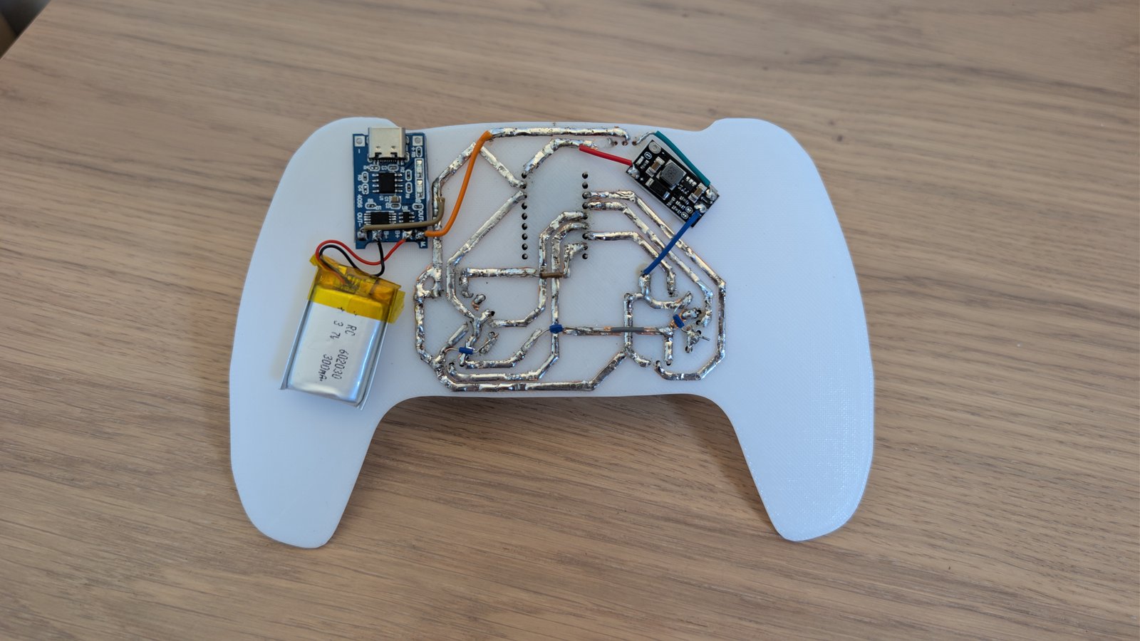 | 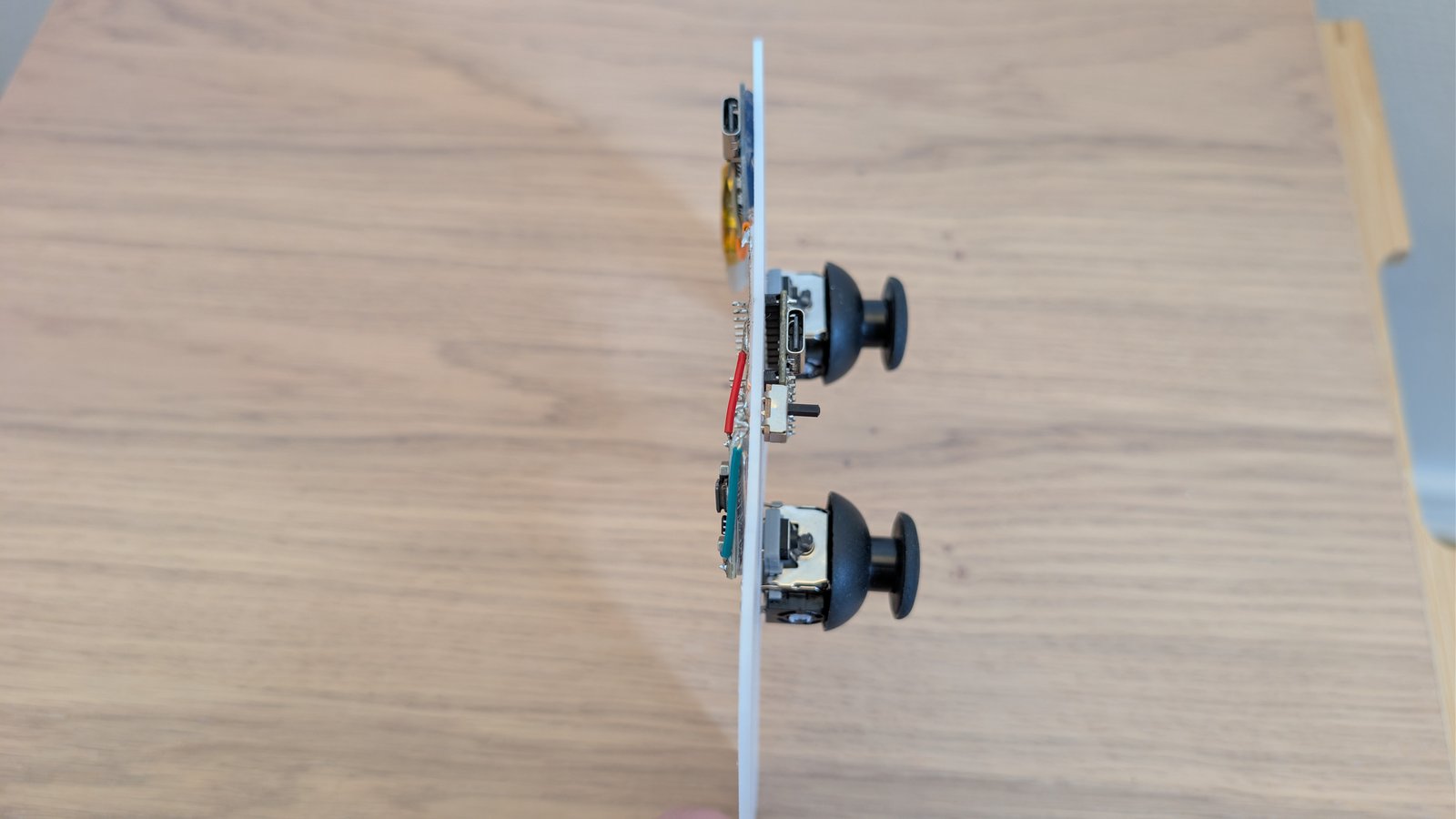 |
The sticks, module and power switch mount on the front; the copper tape and the battery and charger modules sit on the back.
Print esp-controller-pcb/esp-controller-pcb.stl flat with the ridges facing up, no supports.
A 0.4 mm nozzle resolves the 1.5 mm minimum feature comfortably.
Prefer PETG or ABS over PLA: soldering conducts heat into the substrate through the foil, and PLA softens near 60 C, which lets pads shift.
Low-temperature bismuth solder (Sn42Bi58, melting near 138 C) reduces that further, and any wire leaving the board should be strain-relieved because tape pads have little peel strength.
Also published on Thingiverse: https://www.thingiverse.com/thing:7397920
tools/kicad_pcb_to_stl.py builds the solid straight from the .kicad_pcb: outline from Edge.Cuts, copper buffered to its real width and extruded, pad and via holes drilled with an FDM margin, then unioned into one watertight body.
It carries its own dependency metadata, so uv resolves everything on first run:
uv run tools/kicad_pcb_to_stl.py esp-controller-pcb/esp-controller-pcb.kicad_pcb -o esp-controller-pcb/esp-controller-pcb.stl --copper-side top --rotate180--copper-side top makes the copper protrude from the top face, which is the one you tape; --rotate180 negates X and Y to spin the board in plane.
Together they give the orientation of the committed STL.
A fresh run places the solid at the origin and can differ by a couple of triangles, since the boolean triangulation is not deterministic; the geometry is unchanged.
Pass --step out.step for a BREP solid instead, which is the useful form for designing a grip or enclosure against.
All four joystick axes must be on ADC1 - ESP-NOW uses the Wi-Fi radio, which permanently takes over ADC2, so ADC2 pins read garbage while running.
| Signal | GPIO | Notes |
|---|---|---|
| Left joystick X | GPIO1 | ADC1_CH0 |
| Left joystick Y | GPIO2 | ADC1_CH1 |
| Right joystick X | GPIO3 | ADC1_CH2 |
| Right joystick Y | GPIO4 | ADC1_CH3 |
| Left joystick SW | GPIO5 | digital, active-low, pull-up |
| Right joystick SW | GPIO6 | digital, active-low, pull-up |
| Aux button A | GPIO7 | digital, active-low, pull-up |
| Aux button B | GPIO10 | digital, active-low, pull-up |
| Aux button C | GPIO11 | digital, active-low, pull-up |
| Both joysticks VCC | 3V3 | do not use 5V (ADC is 3.3V) |
| Both joysticks GND | GND |
Joystick push-switches use the internal pull-up; pressing pulls the pin to GND.
To change a pin, edit the AXIS_* / PIN_BTN_* defines at the top of
src/main.c.
Broadcast packet (little-endian, packed) - see controller_packet.h:
| Field | Type | Meaning |
|---|---|---|
| version | u8 | protocol version (currently 2) |
| buttons | u8 | bit0=left SW, bit1=right SW, bit2=A, bit3=B, bit4=C |
| left_x | i16 | calibrated/normalized −1000..1000 (0 = centered) |
| left_y | i16 | |
| right_x | i16 | |
| right_y | i16 | |
| seq | u32 | increments every send |
The receiver project should include the same controller_packet.h.
v2 sends normalized signed axes (deadzone + calibration applied on the
controller) instead of the raw ADC counts that v1 sent.
The device exposes a line-based CLI on the USB Serial/JTAG port (115200).
Type commands in pio device monitor, or let the web app
send them. Responses are emitted as one JSON object per line
({"t":"cfg"|"tlm"|"ok"|"err"|"log"|"hello",...}).
| Command | Description |
|---|---|
help | list commands |
get | print current config ({"t":"cfg",...}) |
save | persist config to flash (NVS) |
reset | restore default config (then save to keep) |
deadzone <n> | deadzone in raw counts (0..2000) |
invert <lx|ly|rx|ry> <0|1> | invert an axis |
expo <n> | response curve strength, 0..100 (0 = linear) |
streamhz <n> | telemetry rate, 1..100 Hz |
stream <on|off> | toggle JSON telemetry streaming |
cal start | begin min/max capture |
cal center | capture current rest position as center |
cal stop | end capture |
cal save | persist calibration |
cal reset | restore defaults |
Calibration flow: cal start → sweep both sticks to every extreme →
release and cal center → cal stop → cal save. Config is stored in NVS
and reloaded on boot.
Important: ESP-IDF cannot build under a path that contains spaces, and its tooling does not support the MSYS/Git-Bash shell. Build from PowerShell or
cmd, in a space-free path.
pio run                 # build
pio run -t upload       # flash over the native USB-C port
pio device monitor      # serial console (115200) over USB Serial/JTAG
The Super Mini exposes only its native USB port, so the console is routed over
USB Serial/JTAG (configured in sdkconfig.defaults).
On boot the firmware logs its STA MAC address and channel, then prints a
heartbeat with the live joystick values about once per second.
app/)A Vite + Svelte 5 single-page app that connects to the controller over the Web Serial API, visualizes both joysticks live, and exposes the calibration CLI as buttons/sliders plus a raw console.
Hosted at https://runeharlyk.github.io/esp-now-controller/ - plug the controller in and use it there, no checkout required. Web Serial needs a secure context, which the Pages origin provides.
cd app
pnpm install
pnpm dev         # open the printed http://localhost:5173
Then click Connect device and pick the controller's serial port. Web Serial requires a Chromium browser (Chrome/Edge, desktop) served over https or localhost (the dev server is fine). On connect the app fetches the config and turns telemetry streaming on so the sticks animate immediately.
pnpm build emits a static bundle in app/dist/ (relative asset paths, so it
can be hosted anywhere - or later served from the device itself).
.github/workflows/deploy.yml builds that bundle on every push to main and publishes it to GitHub Pages.
A matching receiver needs to: init Wi-Fi in STA mode on channel 1, init
ESP-NOW, add the broadcast peer (FF:FF:FF:FF:FF:FF), register a receive
callback, and memcpy the incoming bytes into a controller_packet_t.
| Qty | Value | Footprint | References |
|---|---|---|---|
| 2 | JOYSTICK | ctrl:JOYSTICK | U2, U3 |
| 1 | ESP32-S3-SuperMini | ctrl:ESP32-S3-SuperMini | U1 |
| 1 | PWR_IN_2PIN | ctrl:PWR_IN_2PIN | J1 |
| 1 | SW_POWER_3PIN | ctrl:SW_POWER_3PIN | SW1 |
It measures 160 × 106.2 mm and has 2 copper layers, 1.6 mm thick.
5 parts. The full list of its parts is on this page, with links to each part's symbol and footprint where PCBKit's library has them.
From the runeharlyk/esp-now-controller repository on GitHub, at the commit this page was made from: the board is esp-controller-pcb/esp-controller-pcb.kicad_pcb and its schematic esp-controller-pcb/esp-controller-pcb.kicad_sch. PCBKit opens the board in the browser, with nothing to install.
Its repository publishes it under the MIT licence: you may reuse it on that licence's terms (keep the author's notice, and for a copyleft licence share your changes alike).

joypad-ai/joypad-os
Universal controller firmware for building adapters, dongles, and custom controllers.

OLIMEX/OLINUXINO
OLINUXINO is Open Source / Open Hardware, low cost from EUR 24 Linux Industrial grade Single Board Computer capable to operate -25+85C

jamro/tiny-engineer
A small desktop robot that brings an AI coding assistant to life, physically acting out when it reads files, thinks, writes code, and finishes work.

hackclub/OnBoard
💡 Join 1,000 teenagers and make your first PCB with a $100 grant!


Luos-io/luos_engine
Open-source and real-time orchestrator for cyber-physical-systems, to easily design, test and deploy embedded applications and digital twins.