


2 layers142.4 × 117.1 mm
ASME UM High current board
umasme/2025-2026
University of Miami ASME Official Repository for NASA Lunabotics Challenge
93 parts2MIT

 Rudra2002/ComputerControl
The system communicates over MQTT (with WebSocket support), enabling a static web dashboard — deployable on Cloudflare Pages or any CDN — to send commands and receive real-time status updates from anywhere.
Pc power remote switch is an open-source printed circuit board by Rudra2002, from the Rudra2002/ComputerControl repository on GitHub. It is a 2-layer board with 12 parts on 26 nets.
It is built around the WEMOS D1 MINI and 1000UF 16V. Its parts include 4 ICs, 3 resistors, 3 connectors and 2 capacitors. It belongs with the ESP8266 boards of this library.
Remotely power on, restart, and monitor your PC from anywhere in the world — using an ESP32 microcontroller, MQTT, and a sleek web dashboard.




ComputerControl is an IoT project that lets you control your PC's power and restart buttons remotely over the internet. An ESP32 physically connects to your PC's front-panel headers via relay modules and monitors the power LED to detect the PC's on/off state.
The system communicates over MQTT (with WebSocket support), enabling a static web dashboard — deployable on Cloudflare Pages or any CDN — to send commands and receive real-time status updates from anywhere.
┌──────────────────────────────────────────────────────────────────┐
│                        CLOUD / INTERNET                          │
│                                                                  │
│  ┌─────────────────────┐         ┌────────────────────────────┐  │
│  │   Web Dashboard     │◄──WSS──►│     MQTT Broker            │  │
│  │  (Cloudflare Pages) │         │  (broker.emqx.io or self)  │  │
│  │                     │         │                            │  │
│  │  • Power ON/OFF     │         │  Topics:                   │  │
│  │  • Restart          │         │  computercontrol/{id}/...  │  │
│  │  • Live status      │         │    /status                 │  │
│  │  • Activity log     │         │    /command                │  │
│  └─────────────────────┘         │    /response               │  │
│                                  │    /lwt                    │  │
│                                  └────────────┬───────────────┘  │
│                                               │                  │
└───────────────────────────────────────────────┼──────────────────┘
                                                │ MQTT (TCP 1883)
                                                │
┌───────────────────────────────────────────────┼──────────────────┐
│  LOCAL NETWORK                                │                  │
│                                               │                  │
│                        ┌──────────────────────▼───────────────┐  │
│                        │         ESP32 WROOM-32               │  │
│ │ │ │Preferences librarywss:// for TLS-encrypted communicationlocalStorage with base64 encodingThe circuit schematic is designed in KiCad and included in the kicad-circuit/ directory.
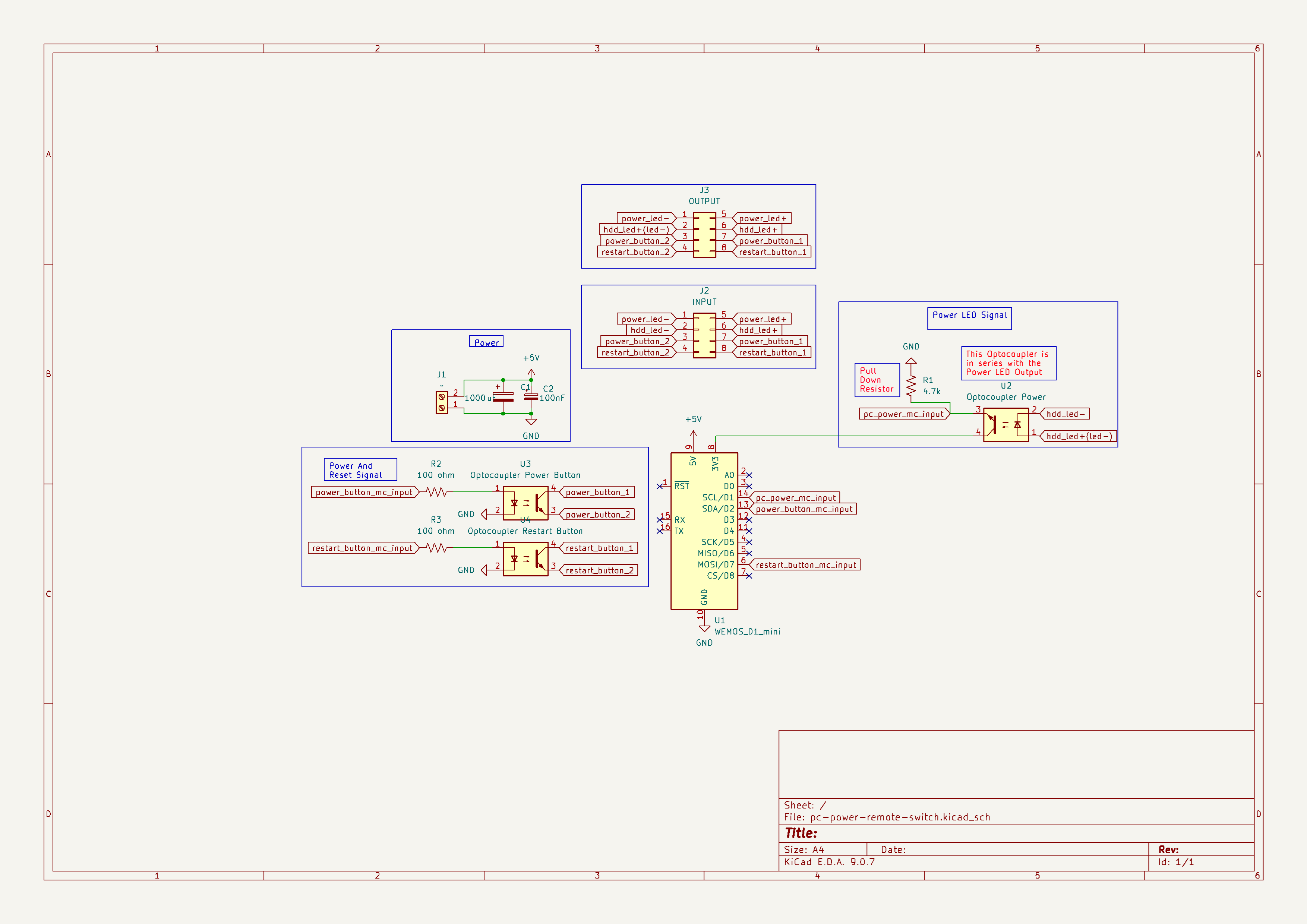
Full schematic available as PDF and SVG. The KiCad project files (
.kicad_sch,.kicad_pcb,.kicad_pro) are also included for editing.
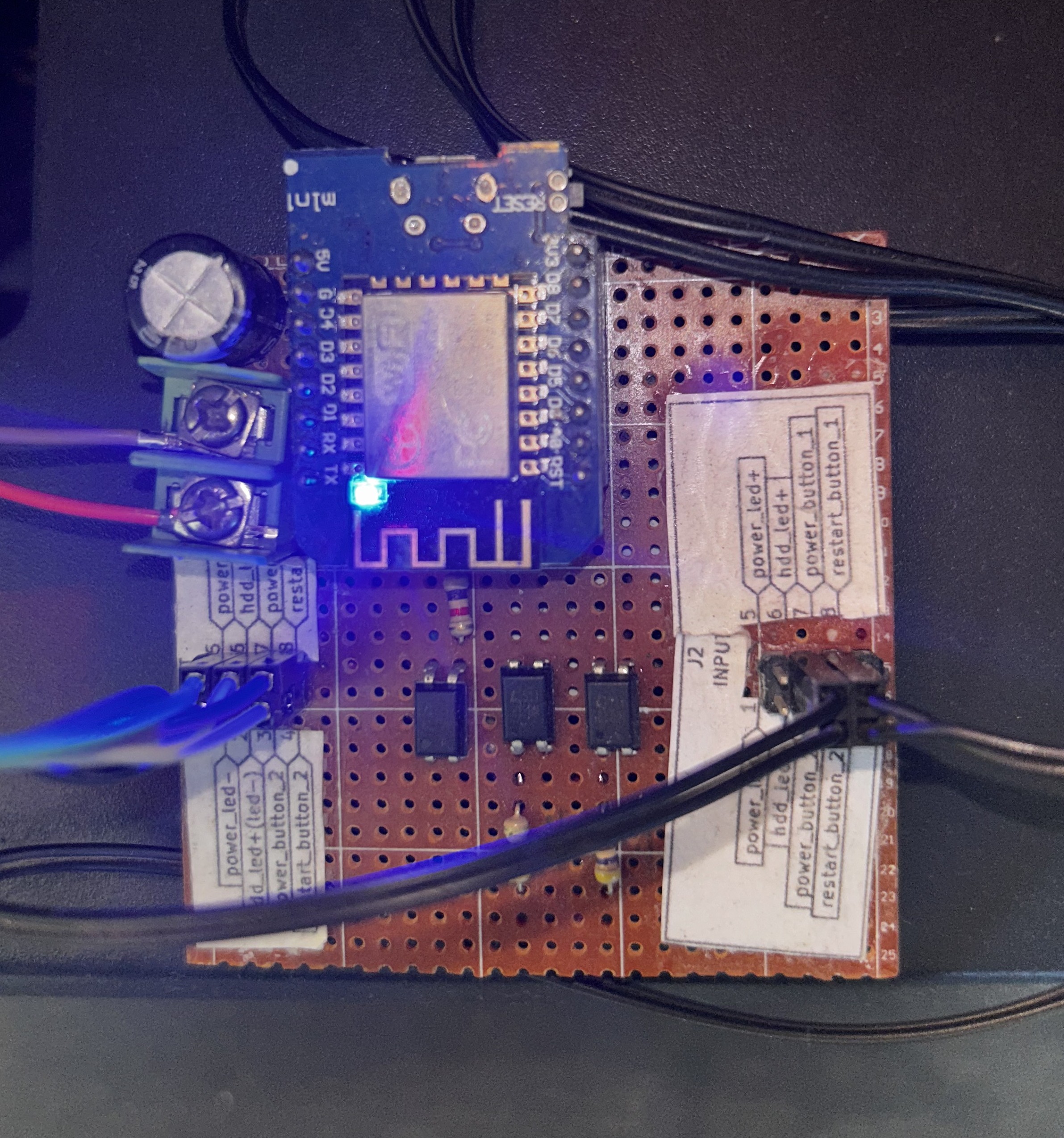
| Component | Connection | Purpose |
|---|---|---|
| Relay Module 1 | ESP32 GPIO 25 → Relay IN | Simulates PC power button press |
| Relay Module 2 | ESP32 GPIO 26 → Relay IN | Simulates PC restart button press |
| Voltage Divider / Optocoupler | PC Power LED → ESP32 GPIO 34 | Safely reads the PC power LED state |
| ESP32 Onboard LED | GPIO 2 | Visual feedback (MQTT connected, boot, etc.) |
The relay outputs connect in parallel to the motherboard's front-panel power switch (PWR_SW) and reset switch (RST_SW) headers. When the ESP32 activates a relay for 500ms, it mimics a physical button press.
Motherboard PWR_SW Header:       Motherboard RST_SW Header:
  ┌───┐                            ┌───┐
  │ + ├──── Relay 1 COM            │ + ├──── Relay 2 COM
  │ - ├──── Relay 1 NO             │ - ├──── Relay 2 NO
  └───┘                            └───┘
⚠️ Note: GPIO 34 is an input-only pin on the ESP32 — perfect for reading the PC power LED but cannot output signals.
| GPIO | Direction | Function | Notes |
|---|---|---|---|
34 | Input | PC Power LED sensor | Input-only GPIO, no internal pull-up |
25 | Output | Power relay trigger | Active HIGH for 500ms |
26 | Output | Restart relay trigger | Active HIGH for 500ms |
2 | Output | Onboard LED | Indicates MQTT connection & boot |
0 | Input | Config reset button | Hold LOW on boot to reset WiFi/MQTT settings |
| Component | Quantity | Notes |
|---|---|---|
| ESP32 WROOM-32 DevKit | 1 | Any ESP32 dev board with GPIO access |
| 5V Relay Module (1-channel) | 2 | One for power, one for restart |
| Jumper Wires (F-F, M-F) | ~10 | For connecting ESP32, relays, and ATX headers |
| USB Cable (Micro-USB / Type-C) | 1 | For flashing and powering the ESP32 |
| PC with ATX Motherboard | 1 | Target PC to control |
| Optocoupler / Voltage divider | 1 | (Optional) For safe PC LED reading via GPIO 34 |
| Tool | Purpose | Install |
|---|---|---|
| PlatformIO | Firmware build & flash | VS Code extension or CLI |
| Node.js (v18+) | Web dashboard development | Download from nodejs.org |
| Git | Version control | Download from git-scm.com |
# Clone the repository
git clone https://github.com/Rudra2002/ComputerControl.git
cd ComputerControl

# Build and upload the firmware
cd firmware
pio run --target upload

# Monitor serial output (optional)
pio device monitor --baud 115200
The firmware automatically installs its dependencies (
PubSubClient,ArduinoJson,WiFiManager) via PlatformIO.
On first boot (or after a config reset), the ESP32 creates a WiFi access point:
| Setting | Value |
|---|---|
| SSID | ComputerControl-Setup |
| Password | setup1234 |
| Portal timeout | 180 seconds |
ComputerControl-Setup WiFi network from your phone or laptopbroker.emqx.io (free public broker)1883 (TCP) or 8084 (WebSocket TLS on EMQX)my-pc-ctrl (used to build MQTT topics)To reset configuration: Hold the BOOT button (GPIO 0) while powering on the ESP32. The LED will blink rapidly, and the captive portal will reappear.
cd web
npm install
npm run dev
# Opens at http://localhost:3000cd web
npm run build
# Output in web/dist/ — deploy this folderwss://broker.emqx.io:8084/mqttAll topics follow the pattern: computercontrol/{device_id}/...
| Topic | Direction | QoS | Payload | Description |
|---|---|---|---|---|
…/status | ESP32 → Web | 0 | {"pc":1,"uptime":3600,"rssi":-55,"ip":"192.168.1.100"} | Periodic status (every 2s) |
…/command | Web → ESP32 | 1 | {"action":"power"} | Send command (power, restart, status) |
…/response | ESP32 → Web | 0 | {"success":true,"message":"Power button pressed"} | Command acknowledgement |
…/lwt | Broker → Web | 1 | {"online":false} | Last Will — sent when ESP32 disconnects |
| Feature | Layer | Description |
|---|---|---|
| WiFiManager Portal | Firmware | No hardcoded WiFi credentials |
| MQTT Authentication | Firmware + Web | Optional username/password for broker access |
| Command Rate Limiting | Firmware | Min 3-second interval between relay commands |
| Topic Namespacing | MQTT | Unique device ID isolates traffic |
| LWT (Last Will) | MQTT | Broker notifies dashboard if ESP32 drops offline |
| WSS (TLS) | Web | Web dashboard connects via encrypted WebSocket |
| Inactivity Auto-Disconnect | Web | Dashboard disconnects after 30 min of inactivity |
| Settings Obfuscation | Web | localStorage settings encoded with base64 |
ComputerControl/
├── firmware/                  # ESP32 firmware (PlatformIO)
│   ├── platformio.ini         # Build config & dependencies
│   └── src/
│       ├── config.h           # Pin definitions, timing, MQTT defaults
│       └── main.cpp           # Main firmware — WiFi, MQTT, relay logic
│
├── web/                       # Web dashboard (Vite + vanilla JS)
│   ├── index.html             # Dashboard HTML (connect screen + dashboard)
│   ├── package.json           # npm dependencies (mqtt.js)
│   ├── vite.config.js         # Vite dev server config
│   └── src/
│       ├── main.js            # MQTT client, UI logic, command handling
│       └── style.css          # Glassmorphism dark theme, animations
│
├── kicad-circuit/             # Hardware schematic (KiCad 8)
│   ├── pc-power-remote-switch.kicad_sch   # Schematic source
│   ├── pc-power-remote-switch.kicad_pcb   # PCB layout
│   ├── pc-power-remote-switch.kicad_pro   # KiCad project file
│   ├── scematic.png           # Schematic render (PNG)
│   ├── scematic.pdf           # Schematic render (PDF)
│   └── pc-power-remote-switch.svg         # Schematic render (SVG)
│
├── LeagacySystem/ # Legacy ESP8266 firmware (archived)The LeagacySystem/ directory contains the original ESP8266-based implementation that served a web dashboard directly from the microcontroller via LittleFS. This has been superseded by the current ESP32 + MQTT architecture, which offers:
The legacy code is kept for reference purposes.
git checkout -b feature/my-feature)git commit -m 'Add my feature')git push origin feature/my-feature)This project is open source and available under the MIT License.
Built with ❤️ using ESP32 + MQTT + Vite
Designed & developed by Rudra
| Qty | Value | Footprint | References |
|---|---|---|---|
| 2 | 100 ohm | Resistor_THT:R_Axial_DIN0207_L6.3mm_D2.5mm_P7.62mm_Horizontal | R2, R3 |
| 1 | 1000 uF | Capacitor_THT:CP_Radial_Tantal_D10.5mm_P5.00mm | C1 |
| 1 | 100nF | Capacitor_THT:CP_Radial_D5.0mm_P2.50mm | C2 |
| 1 | 4.7k | Resistor_THT:R_Axial_DIN0207_L6.3mm_D2.5mm_P7.62mm_Horizontal | R1 |
| 1 | INPUT | Connector_PinSocket_1.27mm:PinSocket_2x04_P1.27mm_Vertical | J2 |
| 1 | OUTPUT | Connector_PinSocket_1.27mm:PinSocket_2x04_P1.27mm_Vertical | J3 |
| 1 | Optocoupler Power | Package_DIP:DIP-4_W7.62mm_Socket_LongPads | U2 |
| 1 | Optocoupler Power Button | Package_DIP:DIP-4_W7.62mm_Socket_LongPads | U3 |
| 1 | Optocoupler Restart Button | Package_DIP:DIP-4_W7.62mm_Socket_LongPads | U4 |
| 1 | WEMOS_D1_mini | RF_Module:WEMOS_D1_mini_light | U1 |
| 1 | ~ | TerminalBlock:TerminalBlock_Altech_AK300-2_P5.00mm | J1 |
12 parts, built around the WEMOS D1 MINI and 1000UF 16V. The full list of its parts is on this page, with links to each part's symbol and footprint where PCBKit's library has them.
From the Rudra2002/ComputerControl repository on GitHub, at the commit this page was made from: the board is kicad-circuit/pc-power-remote-switch.kicad_pcb and its schematic kicad-circuit/pc-power-remote-switch.kicad_sch. PCBKit opens the board in the browser, with nothing to install.
Its repository states no licence, so its author keeps all rights: ask Rudra2002 before reusing the design.
umasme/2025-2026
University of Miami ASME Official Repository for NASA Lunabotics Challenge


arminesweeper/Minesweeper2026
The Assiut Robotics Minesweeper Rover is an autonomous field robotics platform engineered for humanitarian mine action and robotics competitions (Minesweeper International / Minesweeper Egypt).

PedroBMedeiros/PolySaber
Firmware for Cal Poly Senior Project - PolySaber a Custom PCB Soundboard


thejamesrhodes/Hyades-Flight-Computer
Full Hardware and Electronics design, Bare-metal GNC flight software for an actively attitude-controlled high-power rocket

