2 layers19 × 76 mm
Sub
google/mozc-devices
Circuit diagrams and firmware source code for Gboard DIY keyboards
15 parts3kApache-2.0

 rubiconRiver/pax-buttonica
Big glowing turn buttons for Twilight Imperium 4: web app, phone buttons, ESP32 firmware and an open button standard
Pax button is an open-source printed circuit board by rubiconRiver, from the rubiconRiver/pax-buttonica repository on GitHub. It is a 2-layer board with 15 parts on 18 nets, routed with 60 tracks and 0 vias.
Its parts include 3 resistors, 3 connectors, 1 capacitor, 1 IC and 1 diode. It belongs with the ESP32 and RISC-V boards of this library.
A 70 mm round, two-layer board that every part of a button solders onto, so the only loose wires left are three to the LED ring and two to the batteries.
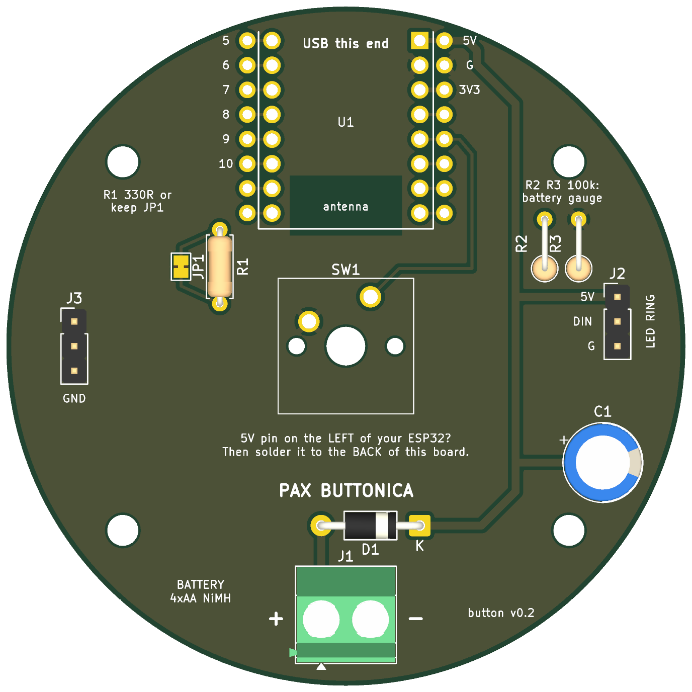
Revision 0.2. Status: designed, rule-checked, never manufactured. (v0.1, the first one ordered, is the same board without R2/R3 and the number box, and with C1 nearer the middle; it works the same.) KiCad's design-rule check passes with no violations and nothing unconnected. No board has been made, and the ESP32 module's footprint was drawn from published dimensions, not from a module in hand. Order a small batch and test one before building six.
| Ref | Part | Notes |
|---|---|---|
| U1 | ESP32-C3 SuperMini | Top of the board, USB-C at the rim. A spare solder hole sits beside every pin, so anything the module can do is reachable later: extra buttons, a speaker amp, battery sensing. |
| SW1 | MX-style keyboard switch | Dead centre. Any Cherry-MX-compatible switch, 3-pin or 5-pin. One side to ground, the other to the 5th pin on the module's power side. |
| J1 | Battery, 4 × AA NiMH | A 5.08 mm screw terminal, or just solder the holder's leads into the holes. + is on the left. |
| D1 | 1N5817 diode | Reverse-polarity protection. Stripe to the right (marked K). |
| C1 | 1000 µF capacitor | Near the rim, below the LED connector, where it clears both the 8-LED and the 50 mm 12-LED ring. Stripe (negative) away from the + mark. |
| R2, R3 | 100 kΩ × 2, optional | A battery gauge: they halve the battery voltage for the ESP32 to read. Fit both and set BATTERY_PIN in the firmware (the fourth pin on the 5V side, usually 4); the test bench and the game then show each button's battery. Leave them off and nothing changes. |
| J2 | LED ring | 5V · DIN · G. Solder the ring's three wires straight in, or fit a pin header. |
| R1 / JP1 | 330 Ω, optional | JP1 is a jumper that is already bridged on the bare board, so with R1 left empty everything works. To use the resistor: fit R1 and cut the thin link between JP1's two pads. |
| J3 | Three ground holes | For the other leg of any extra buttons. |
| H1–H4 | M3 mounting holes | On a 46 × 38 mm rectangle. |
| Back | "No." box | Somewhere to write which button this is. |
The ground is a copper pour on both sides. There is no copper under the module's antenna.
firmware/button/config.h as the first entry of BUTTON_PINS. The LED data line goes to GPIO10, which everyone agrees on.Step by step in docs/HARDWARE.md: diode, ESP32 (on its pin strips, USB off the edge), switch, capacitor, battery leads, LED ring.
Upload pax-button-v0.2-gerbers.zip. The preview should show a round board with a square switch outline in the middle. Then:
The whole board is produced by a script, so changes are reviewable text:
/Applications/KiCad/KiCad.app/Contents/Frameworks/Python.framework/Versions/Current/bin/python3 make_board.py
kicad-cli pcb drc pax-button.kicad_pcb
pax-button.kicad_pcb opens in KiCad 9 or later if you would rather edit it by hand.
| Qty | Value | Footprint | References |
|---|---|---|---|
| 4 | MountingHole_3.2mm_M3 | MountingHole_3.2mm_M3 | H1, H2, H3, H4 |
| 2 | 100k (optional) | R_Axial_DIN0207_L6.3mm_D2.5mm_P5.08mm_Vertical | R2, R3 |
| 1 | 1000uF 16V | CP_Radial_D8.0mm_P3.50mm | C1 |
| 1 | 1N5817 | D_DO-41_SOD81_P10.16mm_Horizontal | D1 |
| 1 | 330R (optional) | R_Axial_DIN0207_L6.3mm_D2.5mm_P7.62mm_Horizontal | R1 |
| 1 | BATTERY 4xAA NiMH | TerminalBlock_Phoenix_MKDS-1,5-2-5.08_1x02_P5.08mm_Horizontal | J1 |
| 1 | ESP32-C3 SuperMini | U1 | |
| 1 | GND x3 | PinHeader_1x03_P2.54mm_Vertical | J3 |
| 1 | LED RING | PinHeader_1x03_P2.54mm_Vertical | J2 |
| 1 | MX switch | SW_Cherry_MX_1.00u_PCB | SW1 |
| 1 | bypass R1 | SolderJumper-2_P1.3mm_Bridged_Pad1.0x1.5mm | JP1 |
15 parts. The full list of its parts is on this page, with links to each part's symbol and footprint where PCBKit's library has them.
From the rubiconRiver/pax-buttonica repository on GitHub, at the commit this page was made from: the board is hardware/pcb/pax-button.kicad_pcb. PCBKit opens the board in the browser, with nothing to install.
Its repository states no licence, so its author keeps all rights: ask rubiconRiver before reusing the design.
google/mozc-devices
Circuit diagrams and firmware source code for Gboard DIY keyboards

hoglet67/RGBtoHDMI
Bare-metal Raspberry Pi project that provides pixel-perfect sampling of Retro Computer RGB/YUV video and conversion to HDMI

mntmn/amiga2000-gfxcard
MNT VA2000, an Open Source Amiga 2/3/4000 Graphics Card (Zorro II/III), written in Verilog

hackclub/OnBoard
💡 Join 1,000 teenagers and make your first PCB with a $100 grant!

kenp-io/not-for-airpods-repairs
The content of this repository is licensed under the WTFPL License. Please have a close look at the terms before using this material.

Luos-io/luos_engine
Open-source and real-time orchestrator for cyber-physical-systems, to easily design, test and deploy embedded applications and digital twins.

Chrismettal/EleLab_v2
Cheap DIY lab system for hobbyists and the tinkering folk
