2 layers19 × 76 mm
Sub
google/mozc-devices
Circuit diagrams and firmware source code for Gboard DIY keyboards
15 parts3kApache-2.0

 rubiconRiver/pax-buttonica
Big glowing turn buttons for Twilight Imperium 4: web app, phone buttons, ESP32 firmware and an open button standard
Pax button is an open-source printed circuit board by rubiconRiver, from the rubiconRiver/pax-buttonica repository on GitHub. It is a 2-layer board with 15 parts on 18 nets, routed with 60 tracks and 0 vias.
Its parts include 3 resistors, 3 connectors, 1 capacitor, 1 IC and 1 diode. It belongs with the ESP32 and RISC-V boards of this library.
A 70 mm round, two-layer board that every part of a button solders onto, so the only loose wires left are three to the LED ring and two to the batteries.
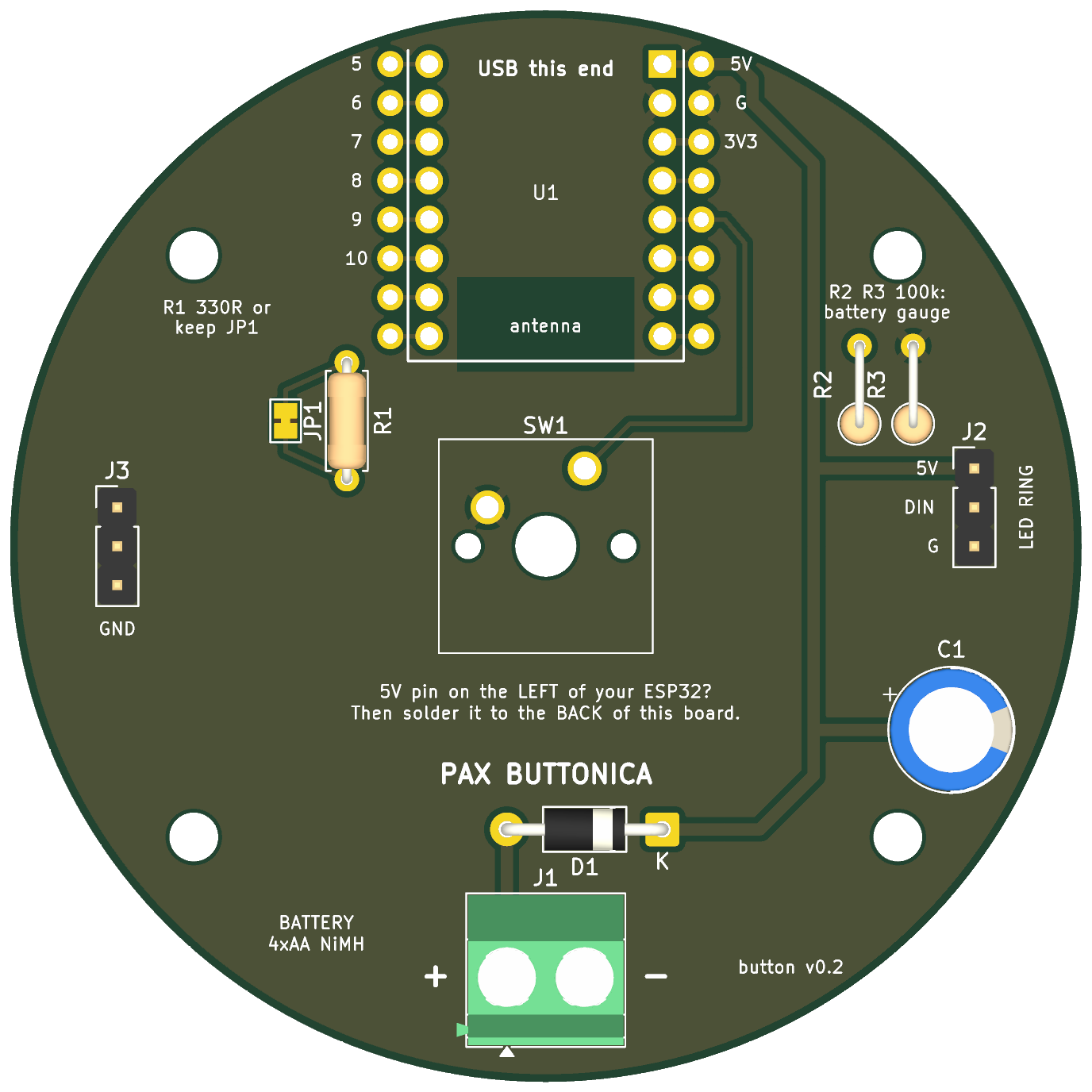
Revision 0.2. Status: designed, rule-checked, never manufactured. (v0.1, the first one ordered, is the same board without R2/R3 and the number box, and with C1 nearer the middle; it works the same.) KiCad's design-rule check passes with no violations and nothing unconnected. No board has been made, and the ESP32 module's footprint was drawn from published dimensions, not from a module in hand. Order a small batch and test one before building six.
| Ref | Part | Notes |
|---|---|---|
| U1 | ESP32-C3 SuperMini | Top of the board, USB-C at the rim. A spare solder hole sits beside every pin, so anything the module can do is reachable later: extra buttons, a speaker amp, battery sensing. |
| SW1 | MX-style keyboard switch | Dead centre. Any Cherry-MX-compatible switch, 3-pin or 5-pin. One side to ground, the other to the 5th pin on the module's power side. |
| J1 | Battery, 4 × AA NiMH | A 5.08 mm screw terminal, or just solder the holder's leads into the holes. + is on the left. |
| D1 | 1N5817 diode | Reverse-polarity protection. Stripe to the right (marked K). |
| C1 | 1000 µF capacitor | Near the rim, below the LED connector, where it clears both the 8-LED and the 50 mm 12-LED ring. Stripe (negative) away from the + mark. |
| R2, R3 | 100 kΩ × 2, optional | A battery gauge: they halve the battery voltage for the ESP32 to read. Fit both and set BATTERY_PIN in the firmware (the fourth pin on the 5V side, usually 4); the test bench and the game then show each button's battery. Leave them off and nothing changes. |
| J2 | LED ring | 5V · DIN · G. Solder the ring's three wires straight in, or fit a pin header. |
| R1 / JP1 | 330 Ω, optional | JP1 is a jumper that is already bridged on the bare board, so with R1 left empty everything works. To use the resistor: fit R1 and cut the thin link between JP1's two pads. |
| J3 | Three ground holes | For the other leg of any extra buttons. |
| H1–H4 | M3 mounting holes | On a 46 × 38 mm rectangle. |
| Back | "No." box | Somewhere to write which button this is. |
The ground is a copper pour on both sides. There is no copper under the module's antenna.
firmware/button/config.h as the first entry of BUTTON_PINS. The LED data line goes to GPIO10, which everyone agrees on.Step by step in docs/HARDWARE.md: diode, ESP32 (on its pin strips, USB off the edge), switch, capacitor, battery leads, LED ring.
Upload pax-button-v0.2-gerbers.zip. The preview should show a round board with a square switch outline in the middle. Then:
The whole board is produced by a script, so changes are reviewable text:
/Applications/KiCad/KiCad.app/Contents/Frameworks/Python.framework/Versions/Current/bin/python3 make_board.py
kicad-cli pcb drc pax-button.kicad_pcb
pax-button.kicad_pcb opens in KiCad 9 or later if you would rather edit it by hand.
| Qty | Value | Footprint | References |
|---|---|---|---|
| 4 | MountingHole_3.2mm_M3 | MountingHole_3.2mm_M3 | H1, H2, H3, H4 |
| 2 | 100k (optional) | R_Axial_DIN0207_L6.3mm_D2.5mm_P5.08mm_Vertical | R2, R3 |
| 1 | 1000uF 16V | CP_Radial_D8.0mm_P3.50mm | C1 |
| 1 | 1N5817 | D_DO-41_SOD81_P10.16mm_Horizontal | D1 |
| 1 | 330R (optional) | R_Axial_DIN0207_L6.3mm_D2.5mm_P7.62mm_Horizontal | R1 |
| 1 | BATTERY 4xAA NiMH | TerminalBlock_Phoenix_MKDS-1,5-2-5.08_1x02_P5.08mm_Horizontal | J1 |
| 1 | ESP32-C3 SuperMini | U1 | |
| 1 | GND x3 | PinHeader_1x03_P2.54mm_Vertical | J3 |
| 1 | LED RING | PinHeader_1x03_P2.54mm_Vertical | J2 |
| 1 | MX switch | SW_Cherry_MX_1.00u_PCB | SW1 |
| 1 | bypass R1 | SolderJumper-2_P1.3mm_Bridged_Pad1.0x1.5mm | JP1 |
google/mozc-devices
Circuit diagrams and firmware source code for Gboard DIY keyboards

hoglet67/RGBtoHDMI
Bare-metal Raspberry Pi project that provides pixel-perfect sampling of Retro Computer RGB/YUV video and conversion to HDMI

mntmn/amiga2000-gfxcard
MNT VA2000, an Open Source Amiga 2/3/4000 Graphics Card (Zorro II/III), written in Verilog

hackclub/OnBoard
💡 Join 1,000 teenagers and make your first PCB with a $100 grant!

kenp-io/not-for-airpods-repairs
The content of this repository is licensed under the WTFPL License. Please have a close look at the terms before using this material.

Luos-io/luos_engine
Open-source and real-time orchestrator for cyber-physical-systems, to easily design, test and deploy embedded applications and digital twins.

Chrismettal/EleLab_v2
Cheap DIY lab system for hobbyists and the tinkering folk

15 parts. The full list of its parts is on this page, with links to each part's symbol and footprint where PCBKit's library has them.
From the rubiconRiver/pax-buttonica repository on GitHub, at the commit this page was made from: the board is hardware/pcb/pax-button.kicad_pcb. PCBKit opens the board in the browser, with nothing to install.
Its repository states no licence, so its author keeps all rights: ask rubiconRiver before reusing the design.