
2 layers216.9 × 86.8 mm
Sweepbling lp pcb
davidphilipbarr/Sweep
Sweep - a small promicro based keyboard inspired by the Ferris.
59 parts2.1k

 rppicomidi/twist42
A USB MIDI controller with 4 endless encoders, 4 128x64 OLED displays, and two buttons; works with Twist VCV Rack plugin
Twist4 is an open-source printed circuit board by rppicomidi, from the rppicomidi/twist4 repository on GitHub. It is a 2-layer board of 115 × 27 mm with 59 parts on 41 nets, routed with 224 tracks and 30 vias.
Its parts include 30 resistors, 9 connectors, 8 capacitors and 4 switches. It belongs with the lEDs and displays boards and the RP2040 boards of this library.
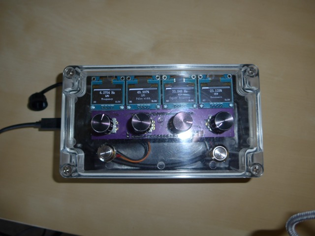
The hardware consists of a Raspberry Pi pico board, 4 EC11-type rotary encoders with push switch, 4 SED1306-based 128x64 OLED display modules, and two pushbutton switches. To maximize the responsiveness of the firmware and to make changing the module I2C addresses unnecessary, each of the 4 OLED displays has its own I2C port. Because the RP2040 only has 2 dedicated hardware I2C ports, the hardware design assumes the firmware will drive the displays using PIO state machine-based I2C ports. Similarly, the hardware design assumes the rotary encoder quadrature encoded A and B lines for each encoder will be decoded using a PIO state machine. Because each PIO contains 4 state machines, dedicating one of the RP2040's 2 PIOs to display I2C ports and the other to quadrature signal decoding is feasible.
A simple RC lowpass filter on each encoder A signal and B signal reduces encoder signal glitches. The Schmitt trigger inputs of the RP2040 chip also help. The remaining resistors are there to pull the GPIO pins high. In all, there are 30 10k resistors and 8 0.01uF capacitors on the board.
The schematic and PCB files were created using KiCad 10.0.
I purchased the unpopulated PCBs from OSH Park because it was convenient for me. If you choose another vendor, please make sure the vendor supports the oval holes that the encoders use. If you must use a service that does not support oval holes (DKRed, for example), you will need to change the encoder footprint for each encoder and adjust the routing as required. I did not publish Gerber files for this project because PCB vendors vary on their requirements. Also, OSH Park normally allows you to submit a KiCad .kicad_pdb file instead of Gerbers, but at the time of this writing, they have not yet updated their support for KiCad 10.0.
This project assumes you are populating the PCBA by hand. The surface mount components are just resistors and capacitors in 0603 packages, so there are no fine pitch ICs to worry about. Because there are components on both sides of the board, some components are hard to solder once other components are in place. Many of the pads of the resistors and capacitors have a connection to the 3.3V power plane or the ground plane. Those planes can act as heat sinks and make the pads more difficult to solder. If you are solder tacking the resistor or capacitor to one pad and then soldering the other, I recommend tacking the pad that is not connected to the power or ground plane first. This will help prevent "tombstoning" and other frustrations.
I recommend soldering components in the following order:
There are holes in the PCB that are slightly oversized for M2 machine screws. I used these holes to attach the display modules to the board before soldering. The oversized holes allow you to slightly adjust the alignment of all 4 displays so they are straight. The screws hold the boards in place to make soldering easier. The AITRIP OLED modules I used had the headers already soldered. I recommend trimming the leads some before soldering to encourage the solder to attach to the PCB instead of wicking up the leads. You may find the VCC and GND pins are difficult to solder because the power plane and ground plane act as head sinks.
I recommend soldering the encoders from the top before soldering them to the bottom to make sure they are flush to the board.
To test the PCB Assembly (PCBA), plug the Pico board to the 2 20-pin sockets. Take care that the VBus pin on the Pico board is connected to the correct socket pin. Connect the pushbutton switches to the 2-pin headers. Load firmware to the board and make sure all 4 OLED displays work. Verify that the computer enumerates the board as a USB MIDI device named twist4. Use a MIDI monitor program such as Pocket MIDI for PC or Mac or the amidi command line utility for Linux to verify that the encoder twists, the encoder switch presses, and the bank button presses send MIDI messages. If it all works, then get ready to put it in an enclosure.
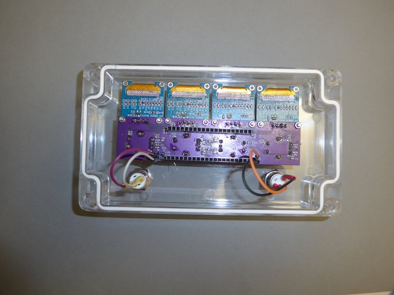
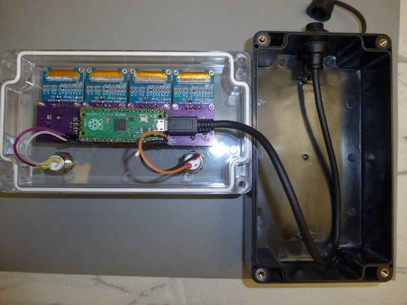
The PCBA attaches to the enclosure using the threaded encoder bushings and the nuts that come with the encoders. The push switches each mount to the enclosure the hardware that comes with each switch.
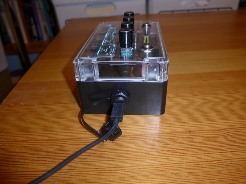
Test the assembled fully populated and solderd PCBA before you mount the assembly in an enclosure. You will need to drill 6 holes in the clear polycarbonate enclosure lid for the encoders and the pushbuttons, and one hole on the side of the enclosure for the USB connector. The hole for the USB connector can be any size between 12mm and 16mm. I centered it on the left side of the enclosure. Make sure you remove burrs and drilling debris when you are done.
Drilling the polycarbonate lid is much less forgiving because the holes for all 4 encoders need to be spaced properly, and the line of the encoders has to be parallel to the long edge of the lid. I printed the top silkscreen layer of the board and used the cross mark inside the circle that marked each encoder shaft location as a drilling template. I aligned this on my enclosure lid by eye, which was a mistake. I would use an adjustable square to align the template if I did it again. I drilled small 1/8" pilot holes and then slowly redrilled the holes with progressively larger drills until the encoders fit. The encoder bushings require holes for M7 machine screws. The encoders I used have anti-rotation tabs that prevent the encoders from screwing all the way flush with the lid. To accommodate those, I mounted the PCBA in the holes I drilled for the encoders. I could see the anti-rotation tabs through the plastic. I used a permanent marker to mark the locations of tabs. Then I removed the PCBA and drilled a 3/32" hole in the location I marked. Then I used a precision file to enlarge the holes until all encoders mounted flush to plastic lid. Finally, I drilled mounting holes for the push switches. I aligned those by eye. Again, I should probably have used an adjustable square. Once I had all the holes drilled, I carefully removed burrs and drilling debris, cleanded the lid with soap and water, and then dried the lid with a microfiber cloth. If any dust or bit of drilling waste sticks to an OLED panel or the the inside of the polycarbonate lid, you will see it and it will annoy you.
Mount the micro USB adapter cable to the side of the box. Optionally, fit the gasket seal under the polycarbonate lid. Mount the PCBA to the box lid. Plug the Micro USB adapter cable to the Pico board. Mount the two pushbutton switches to the box lid. Connect the switches to 2-pin connectors on the PCBA. Run through the tests to make sure everything still works. Screw the lid to the enclosure. Test one more time. You are done.
| Qty | Value | Footprint | References |
|---|---|---|---|
| 30 | 10k | Resistor_SMD:R_0603_1608Metric_Pad0.98x0.95mm_HandSolder | R1, R2, R10, R11, R12, R13, R14, R15, R16, R17, R18, R19, R20, R21, R22, R23 +14 |
| 8 | 0.01uF | Capacitor_SMD:C_0603_1608Metric_Pad1.08x0.95mm_HandSolder | C1, C2, C3, C4, C5, C6, C7, C8 |
| 8 | MountingHole | MountingHole:MountingHole_2.5mm | H1, H2, H3, H4, H5, H6, H7, H8 |
| 4 | OLED Module Connector | Connector_PinSocket_2.54mm:PinSocket_1x04_P2.54mm_Vertical | J4, J7, J8, J9 |
| 4 | RotaryEncoder_Switch | Rotary_Encoder:RotaryEncoder_Alps_EC11E-Switch_Vertical_H20mm | SW1, SW2, SW3, SW4 |
| 1 | Bank 1 | Connector_PinHeader_2.54mm:PinHeader_1x02_P2.54mm_Vertical | J3 |
| 1 | Bank 2 | Connector_PinHeader_2.54mm:PinHeader_1x02_P2.54mm_Vertical | J2 |
| 1 | Debug UART | Connector_PinHeader_2.54mm:PinHeader_1x02_P2.54mm_Vertical | J1 |
| 1 | Pico 1-20 | Connector_PinSocket_2.54mm:PinSocket_1x20_P2.54mm_Vertical | J5 |
| 1 | Pico 21-40 | Connector_PinSocket_2.54mm:PinSocket_1x20_P2.54mm_Vertical | J6 |
davidphilipbarr/Sweep
Sweep - a small promicro based keyboard inspired by the Ferris.


VoronDesign/Voron-Hardware
Cool Hardware designed by the Voron Design group


dmcke5/NucDeck
The Open Source DIY Handheld Gaming PC!

jackw01/scanlight
A better light source for scanning color negative film

ChrisChrisLoLo/beyblock20
The magnetic, modular, 20-key macropad that can join together to form an ortholinear board

sadekbaroudi/vik
This is a VIK module designed to mount a PER56 scroll ring, with a 35mm Cirque Trackpad and optional WS2812B LEDs.
It measures 115 × 27 mm and has 2 copper layers, 1.6 mm thick.
59 parts. The full list of its parts is on this page, with links to each part's symbol and footprint where PCBKit's library has them.
From the rppicomidi/twist4 repository on GitHub, at the commit this page was made from: the board is hardware/twist4/twist4.kicad_pcb and its schematic hardware/twist4/oled-encoder-channel.kicad_sch. PCBKit opens the board in the browser, with nothing to install.
Its repository states no licence, so its author keeps all rights: ask rppicomidi before reusing the design.