4 layers49 × 34 mm
C92 decoder A1
slonket/c92-decoder
An MM1/MM2/Lenz decoder for classic Märklin locomotives and the pre-mfx digital systems.
93 partsCERN-OHL-S-2.0
 RoseDaggerDev/MiniOscilloscope1
Through-Hole Version: Its been fully tested and works like a charm. Its got a BOM of 87 components and fits on a 50x50mm 2-layer board, manufactured by PCBWay.
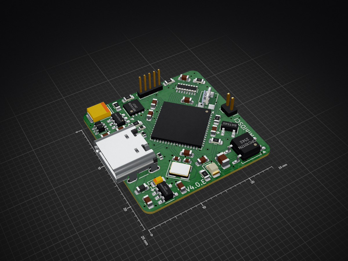
MiniOSCI is an open-source printed circuit board by RoseDaggerDev, from the RoseDaggerDev/MiniOscilloscope repository on GitHub, published under the MIT licence. It is a 4-layer board of 25 × 25 mm with 80 parts on 97 nets, routed with 676 tracks and 87 vias.
It is built around the MIC4428YM, CPC1017N and TLV75533PDBV, with the BAT54S, BAT54SDW and DMC3071LVT-7 among its other parts. Its parts include 34 capacitors, 26 resistors, 6 ICs, 5 diodes and 3 connectors.


This is a little hobby project, taking the EDU09 digital oscilloscope kit from Velleman and redesigning it. I made a through-hole version using the same components as the Velleman kit. And a SMD version using all original parts.
Through-Hole Version: Its been fully tested and works like a charm. Its got a BOM of 87 components and fits on a 50x50mm 2-layer board, manufactured by PCBWay. It took around 3.5 hours to solder after prepping all the components. I underestimated the IC socket size, so things got a bit tight with some parts had to be nudged sideways. I also used the wrong footprint size for the ceramic caps, so they’re a little squished, but everything still worked out in the end!
SMD Version: The SMD version is a compact 25x25mm 4-layer board printed by JLCPCB. It has a BOM of 97 components, including 3 QFNs and four 0402-sized parts, the rest mostly 0603s and SOPs. It took me about 5 hours to solder under a digital microscope, using a hot air rework station and freehanded solder paste. There’s one visible bridge in the upper middle that I’ll clean up later. It’s not really an issue as those pins are already connected by a trace, but it will look cleaner. There’s also some solder blobbing that could be tidied up, but hey, it’s functional (or it will be).
Power rails are looking good, 5V and 3.3V are where they should be, and I’ve confirmed there are no shorts or open circuits on the test points. I haven’t flashed firmware yet because it turns out my old PicKit 3 is too old for the PIC I used, so I’m waiting on a new flasher before I can give it a real test.
Background: The through-hole version was a university project, while the SMD version was my own follow-up challenge. I reverse-engineered the component choices from the original Velleman oscilloscope kit, looking up datasheets and selecting alternatives with similar or improved specs. The original Velleman was around 100x100mm. My through-hole version shrank it to 50x50mm (¼ the size), and the SMD version again cut that down to 25x25mm, or just 1/16 the original footprint. Everything was designed in Proteus 5, since that’s what we use at university.
All in all, I’m really happy with how this turned out. It’s my first full SMD design and soldering job, and despite a few cosmetic hiccups, I think it came together nicely. The through-hole version could have looked neater, but given the part constraints of only using the Velleman kit parts, I’m proud of how compact I got it
| Qty | Value | Footprint | References |
|---|---|---|---|
| 10 | 100n | Capacitor_SMD:C_0603_1608Metric | C3, C4, C5, C11, C12, C13, C19, C27, C28, C35 |
| 8 | 1u | Capacitor_SMD:C_0603_1608Metric | C6, C7, C10, C15, C18, C23, C25, C33 |
| 5 | 1k | Resistor_SMD:R_0603_1608Metric | R1, R16, R17, R18, R24 |
| 3 | 20k | Resistor_SMD:R_0603_1608Metric | R11, R14, R21 |
| 2 | 100 | Resistor_SMD:R_0603_1608Metric | R3, R4 |
| 2 | 100u | Capacitor_Tantalum_SMD:CP_EIA-3528-12_Kemet-T | C1, C17 |
| 2 | 10k | Resistor_SMD:R_0603_1608Metric | R2, R13 |
| 2 | 150 | Resistor_SMD:R_0603_1608Metric | R8, R9 |
| 2 | 20p | Capacitor_SMD:C_0402_1005Metric | C8, C9 |
| 2 | 5.1k | Resistor_SMD:R_0402_1005Metric | R5, R6 |
| 2 | BAT54S | Package_TO_SOT_SMD:SOT-23-3 | D4, D5 |
| 1 | 100 | Resistor_SMD:R_0402_1005Metric | R7 |
| 1 | 100k | Resistor_SMD:R_0603_1608Metric | R25 |
| 1 | 100p | Capacitor_SMD:C_0603_1608Metric | C21 |
| 1 | 10p | Capacitor_SMD:C_0603_1608Metric | C32 |
| 1 | 10u | Capacitor_SMD:C_0805_2012Metric | C20 |
| 1 | 10u | Capacitor_Tantalum_SMD:CP_EIA-1608-08_AVX-J | C16 |
| 1 | 11k | Resistor_SMD:R_0603_1608Metric | R20 |
| 1 | 15k | Resistor_SMD:R_0603_1608Metric | R23 |
| 1 | 15p | Capacitor_SMD:C_0603_1608Metric | C30 |
| 1 | 1k5 | Resistor_SMD:R_0603_1608Metric | R15 |
| 1 | 1n | Capacitor_SMD:C_0603_1608Metric | C2 |
| 1 | 1u | Capacitor_SMD:C_0805_2012Metric | C14 |
| 1 | 2.2 | Resistor_SMD:R_0603_1608Metric | R26 |
| 1 | 2k7 | Resistor_SMD:R_0603_1608Metric | R12 |
| 1 | 2p2 | Capacitor_SMD:C_0603_1608Metric | C26 |
| 1 | 4052 | Package_DFN_QFN:DHVQFN-16-1EP_2.5x3.5mm_P0.5mm_EP1x2mm | U7 |
| 1 | 470p | Capacitor_SMD:C_0603_1608Metric | C24 |
| 1 | 47p | Capacitor_SMD:C_0603_1608Metric | C29 |
| 1 | 5k | Potentiometer_SMD:Potentiometer_Bourns_TC33X_Vertical | RV1 |
| 1 | 5k1 | Resistor_SMD:R_0603_1608Metric | R10 |
| 1 | 680p | Capacitor_SMD:C_0603_1608Metric | C22 |
| 1 | 6p8 | Capacitor_SMD:C_0603_1608Metric | C31 |
| 1 | 75k | Resistor_SMD:R_0603_1608Metric | R22 |
| 1 | 7k5 | Resistor_SMD:R_0603_1608Metric | R19 |
| 1 | BAT54SDW | Package_TO_SOT_SMD:SOT-363_SC-70-6 | D1 |
| 1 | BZX84Cxx | Package_TO_SOT_SMD:SOT-23 | D3 |
| 1 | CPC1017N | Package_SO:SOP-4_3.8x4.1mm_P2.54mm | U2 |
| 1 | Conn_01x02_Pin | Connector_PinHeader_1.27mm:PinHeader_1x02_P1.27mm_Vertical | J3 |
| 1 | Conn_01x05_Pin | Connector_PinHeader_1.00mm:PinHeader_1x05_P1.00mm_Vertical | J1 |
| 1 | Crystal_GND24 | Crystal:Crystal_SMD_3225-4Pin_3.2x2.5mm | Y1 |
| 1 | DMC3071LVT | Package_TO_SOT_SMD:TSOT-23-6 | Q1 |
| 1 | L | Inductor_SMD:L_0603_1608Metric | L1 |
| 1 | LED | LED_SMD:LED_0805_2012Metric | D2 |
| 1 | LOGO | LOGO | G*** |
| 1 | MIC4428 | Package_DFN_QFN:DFN-8-1EP_3x3mm_P0.65mm_EP1.7x2.05mm | U1 |
| 1 | R_Pack08 | Resistor_SMD:R_Array_Convex_8x0602 | RN1 |
| 1 | TLV75533PDBV | Package_TO_SOT_SMD:SOT-23-5 | U4 |
| 1 | TLV9062xDSG | Package_SON:WSON-8-1EP_2x2mm_P0.5mm_EP0.9x1.6mm | U5 |
| 1 | USB_C_Receptacle_USB2.0_16P | Connector_USB:USB_C_Receptacle_GCT_USB4105-xx-A_16P_TopMnt_Horizontal | J2 |
| 1 | ~ | Package_DFN_QFN:VQFN-64-1EP_9x9mm_P0.5mm_EP7.15x7.15mm | U3 |
It measures 25 × 25 mm and has 4 copper layers, 0.6 mm thick.
80 parts, built around the MIC4428YM, CPC1017N, TLV75533PDBV and BAT54S. The full list of its parts is on this page, with links to each part's symbol and footprint where PCBKit's library has them.
From the RoseDaggerDev/MiniOscilloscope repository on GitHub, at the commit this page was made from: the board is KiCAD/MiniOSCI/MiniOSCI.kicad_pcb and its schematic KiCAD/MiniOSCI/MiniOSCI.kicad_sch. PCBKit opens the board in the browser, with nothing to install.
Its repository publishes it under the MIT licence: you may reuse it on that licence's terms (keep the author's notice, and for a copyleft licence share your changes alike).
slonket/c92-decoder
An MM1/MM2/Lenz decoder for classic Märklin locomotives and the pre-mfx digital systems.

cuteboy0323/1590A
These are not at all useful, but having done guitar pedal board kit builds, I decided I should try to make something from scratch.

TrendBit/SMBR-hardware
Design file for SMBR hardware modules in KiCAD.


biomimetics/MRIRobot_PCB
PC boards for MRI robogt control, specifically for STM32 motherboard
