2 layers100 × 100 mm
Explorer
anyshake/explorer
🌏 Detecting seismic wave using 3 geophones and 3-axis accelerometer, pack & send data to AnyShake Observer over RS232 / RS485 serial.
266 parts100
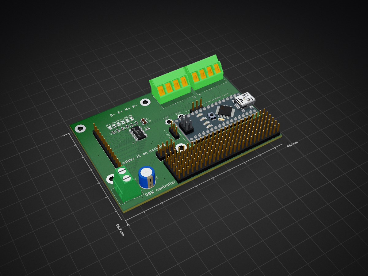
 RocketEDA/Drive-By-Wire-controller
DISCLAIMER: Please read the LICENSE file. Electronic throttle body control is not for the faint of heart. It can result in injury or death of road users.
ThrottleControlBoard is an open-source printed circuit board by RocketEDA, from the RocketEDA/Drive-By-Wire-controller repository on GitHub. It is a 2-layer board of 95.1 × 65.7 mm with 48 parts on 205 nets, routed with 218 tracks and 47 vias.
It is built around the PCA9685PW and SMAJ5.0CA. Its parts include 12 resistors, 8 capacitors, 8 connectors, 4 diodes and 1 IC. It belongs with the AVR (ATmega, ATtiny) boards of this library.


DISCLAIMER: Please read the LICENSE file. Electronic throttle body control is not for the faint of heart. It can result in injury or death of road users. Test, verify, and test again before using on a road with other people. Understand the software and hardware, how they interact, apply good engineering principles and common sense. As stated in the LICENSE file, by using this project in any way, you agree to take on full responsibilities to damages caused by this project.
Drive by wire controller, maps throttle to throttle body 1:1 with idle control
For my application I used a Chrysler/mercedes 75mm throttle body with a corvette c6 throttle pedal. P/N 0280750570 P/N 25835421
SOFTWARE: Code is fully commented.
Schematic description:
arduino nano handles all the code and control.
D2 has an input for switch SW2, signaling to enter setup mode
A6 has a potentiometer, handling idle control.
For servo drive a BTS7960 module from amazon is used.
PCA9685 is used for better PWM control. PWM0 and PWM is used for the BTS, the rest are open
Optionally popuplate R11 and R12. The chrylser TB used a HAR3726 magnetic sensor which specifies for a 10k RL
Assembly notes:
The capacitor and terminal blocks will need to moved to the other side on the BTS7960 to clear. I took this opportunity to upsize the capacitor as well, not sure if there's any appreciatable benefit.
J2 and J4 connect to the TB TPS and e-pedal TPS.
Both e-pedal TPS's are positive direction, aka voltage increases as TPS approaches "open"
TB TPS has one signal inverted. To change this the calculation can be modified:
Upon first run, the "setup" switch should be set. Plugin a USB and set baud to 115200 to follow setup instructions. The potentiometer sets idle (minimum) throttle position. The equation is as follows. Insert a DMM probe between GND and IDLE to measure the pot's voltage. The idle % equation is: Idle position % = (IDLE voltage / 5) * (MAX_IDLE_TB_OPEN / 1023) * 100
| Qty | Value | Footprint | References |
|---|---|---|---|
| 12 | 10k | Resistor_SMD:R_0603_1608Metric_Pad0.98x0.95mm_HandSolder | R1, R2, R3, R4, R5, R6, R7, R8, R9, R10, R11, R12 |
| 6 | SolderJumper_2_Open | Jumper:SolderJumper-2_P1.3mm_Open_TrianglePad1.0x1.5mm | JP0, JP1, JP2, JP3, JP4, JP5 |
| 5 | 1nF | Capacitor_SMD:C_0805_2012Metric_Pad1.18x1.45mm_HandSolder | C3, C4, C5, C6, C7 |
| 4 | SMAJ5.0CA | Diode_SMD:D_SMA | D2, D4, D9, D17 |
| 3 | Conn_02x25_Odd_Even | Connector_PinHeader_2.54mm:PinHeader_2x25_P2.54mm_Vertical | J6, J7, J10 |
| 1 | 100nF | Capacitor_SMD:C_0805_2012Metric_Pad1.18x1.45mm_HandSolder | C2 |
| 1 | 10uF | Capacitor_SMD:C_0805_2012Metric_Pad1.18x1.45mm_HandSolder | C1 |
| 1 | 470uF | Capacitor_THT:CP_Radial_D8.0mm_P3.50mm | C8 |
| 1 | 5V | TerminalBlock:TerminalBlock_Altech_AK300-2_P5.00mm | J5 |
| 1 | Arduino_Nano_Every | Module:Arduino_Nano | A1 |
| 1 | BTS7960 module | Connector_PinHeader_2.54mm:PinHeader_2x04_P2.54mm_Vertical | J1 |
| 1 | Conn_01x14 | Connector_PinHeader_2.54mm:PinHeader_1x14_P2.54mm_Vertical | J3 |
| 1 | GND | TestPoint:TestPoint_Loop_D3.80mm_Drill2.5mm | TP2 |
| 1 | IDLE | TestPoint:TestPoint_Loop_D3.80mm_Drill2.5mm | TP1 |
| 1 | PCA9685PW | Package_SO:TSSOP-28_4.4x9.7mm_P0.65mm | U1 |
| 1 | R_Potentiometer_Trim | Connector_PinHeader_2.54mm:PinHeader_1x03_P2.54mm_Vertical | RV1 |
| 1 | SW_SPDT | Connector_PinHeader_2.54mm:PinHeader_1x03_P2.54mm_Vertical | SW2 |
| 1 | TB TPS | TerminalBlock:TerminalBlock_Altech_AK300-4_P5.00mm | J4 |
| 1 | e-Throttle | TerminalBlock:TerminalBlock_Altech_AK300-4_P5.00mm | J2 |
The 44 most common of 48 parts.
It measures 95.1 × 65.7 mm and has 2 copper layers, 1.6 mm thick.
48 parts, built around the PCA9685PW and SMAJ5.0CA. The full list of its parts is on this page, with links to each part's symbol and footprint where PCBKit's library has them.
From the RocketEDA/Drive-By-Wire-controller repository on GitHub, at the commit this page was made from: the board is ThrottleControlBoard/ThrottleControlBoard.kicad_pcb and its schematic ThrottleControlBoard/ThrottleControlBoard.kicad_sch. PCBKit opens the board in the browser, with nothing to install.
Its repository states no licence, so its author keeps all rights: ask RocketEDA before reusing the design.
anyshake/explorer
🌏 Detecting seismic wave using 3 geophones and 3-axis accelerometer, pack & send data to AnyShake Observer over RS232 / RS485 serial.

BYU-I-eBadge/e-badge
A hackable eBadge platform for students — a customizable, programmable electronics badge designed for hands-on learning and creative exploration throughout their academic journey.


ParadigmEngineering/igvc-2023-hardware
Intelligent Ground Vehicle Competition (Spring 2023) hardware for the Paradigm Engineering Student Group

victorstoica114/UWB_Module_ESP_IDF
ESP-IDF 6.0.2 firmware for the custom UWB Module V1.0 Rev.B, based on an ESP32-S3-WROOM-1-N16R8. The same application image runs on every module; persistent identity and runtime configuration select the role and active…

vincentchen18/polyphonic-synthesizer
a 2 octave pcb musical instrument!!! :)))
