2 layers37 × 19 mm
Passive rpi hub75-adapter
hzeller/rpi-rgb-led-matrix
Controlling up to three chains of 64x64, 32x32, 16x32 or similar RGB LED displays using Raspberry Pi GPIO
2 parts4.4kGPL-2.0

 robotont/robotont-electronics-battery-adapter
Adapter PCB for connecting the data pins to the Robotont gen 3 battery.
Robotont electronics battery adapter is an open-source printed circuit board by robotont, from the robotont/robotont-electronics-battery-adapter repository on GitHub, published under the CERN-OHL-P-2.0 licence. It is a 2-layer board of 23.5 × 15 mm with 2 parts on 8 nets, routed with 32 tracks and 0 vias.
It is built around the GT-BTP25006-0240A-010A. It belongs with the interfaces and adapters and power boards of this library.
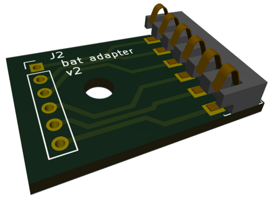
The repository contains KiCAD schematics and PCB layout for the battery adapter. By connecting the data pins, Robotont is able to communicate with the battery onewire interface and monitor the battery status. The Production folder contains prepared gerbers and BOM ready to order from e.g. JLCPCB.
Use the files in jlcpcb/production_files for manufacturing and assembly.
[!IMPORTANT] Set PCB thickness to 1.0 mm. This is required for a smooth fit with the 3D-printed body.
GERBER-robotont-electronics-battery-adapter.zip) to the JLCPCB PCB order wizard.BOM-robotont-electronics-battery-adapter.csv) and CPL (CPL-robotont-electronics-battery-adapter.csv) in the assembly wizard.git clone https://github.com/robotont/robotont-electronics-battery-adapter.gitIf you're on Ubuntu, here's a snippet:
sudo add-apt-repository ppa:kicad/kicad-9.0-releases -y
sudo apt update
sudo apt install --install-recommends kicadThe JLCPCB plugin is required to manage rotations and generate production files. Installation instructions are available in the plugin repository: https://github.com/Bouni/kicad-jlcpcb-tools
robotont-electronics-battery-adapter.kicad_pro in KiCAD.jlcpcb/production_files/rotations.csv as the rotation rules file.| Schematic | Layout |
|---|---|
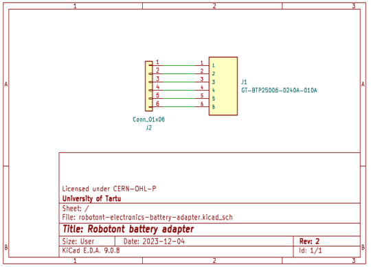 | 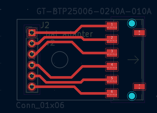 |
| Qty | Value | Footprint | References |
|---|---|---|---|
| 1 | Conn_01x06 | Connector_PinHeader_2.00mm:PinHeader_1x06_P2.00mm_Vertical | J2 |
| 1 | GT-BTP25006-0240A-010A | GT-BTP25006-0240A-010A:GT-BTP25006-0240A-010A | J1 |
hzeller/rpi-rgb-led-matrix
Controlling up to three chains of 64x64, 32x32, 16x32 or similar RGB LED displays using Raspberry Pi GPIO


adamws/kicad-kbplacer
KiCad plugin for automatic keyboard's key placement and routing

Luos-io/luos_engine
Open-source and real-time orchestrator for cyber-physical-systems, to easily design, test and deploy embedded applications and digital twins.

NVNTLabs/switch2-SDEX2M2
Micro SD Express to M.2 NVME Adapter for Nintendo Switch 2

BlueSCSI/BlueSCSI-v2
BlueSCSI v2/Ultra - an open source, open hardware, SCSI emulator using the Pi Pico PR2040 and Pico 2 RP2350

ohmtech-rdi/eurorack-blocks
Software to Hardware Prototyping for Eurorack using C++, Max/Gen~ or Faust

It measures 23.5 × 15 mm and has 2 copper layers, 1 mm thick.
2 parts, built around the GT-BTP25006-0240A-010A. The full list of its parts is on this page, with links to each part's symbol and footprint where PCBKit's library has them.
From the robotont/robotont-electronics-battery-adapter repository on GitHub, at the commit this page was made from: the board is robotont-electronics-battery-adapter.kicad_pcb and its schematic robotont-electronics-battery-adapter.kicad_sch. PCBKit opens the board in the browser, with nothing to install.
Its repository publishes it under the CERN-OHL-P-2.0 licence: you may reuse it on that licence's terms (keep the author's notice, and for a copyleft licence share your changes alike).