

4 layers94 × 50.8 mm

A replacement controller board for the Apple UniDisk 3.5 (A2M2053).
A2m2053 is an open-source printed circuit board by robertrico, from the robertrico/a2m2053_controller repository on GitHub. It is a 2-layer board of 100 × 110 mm with 46 parts on 80 nets, routed with 768 tracks and 123 vias.
It is built around the STPS2L40AF. Its parts include 18 resistors, 13 capacitors, 5 ICs, 5 connectors and 1 diode. It belongs with the RP2040 boards of this library.
A replacement controller board for the Apple UniDisk 3.5 (A2M2053).
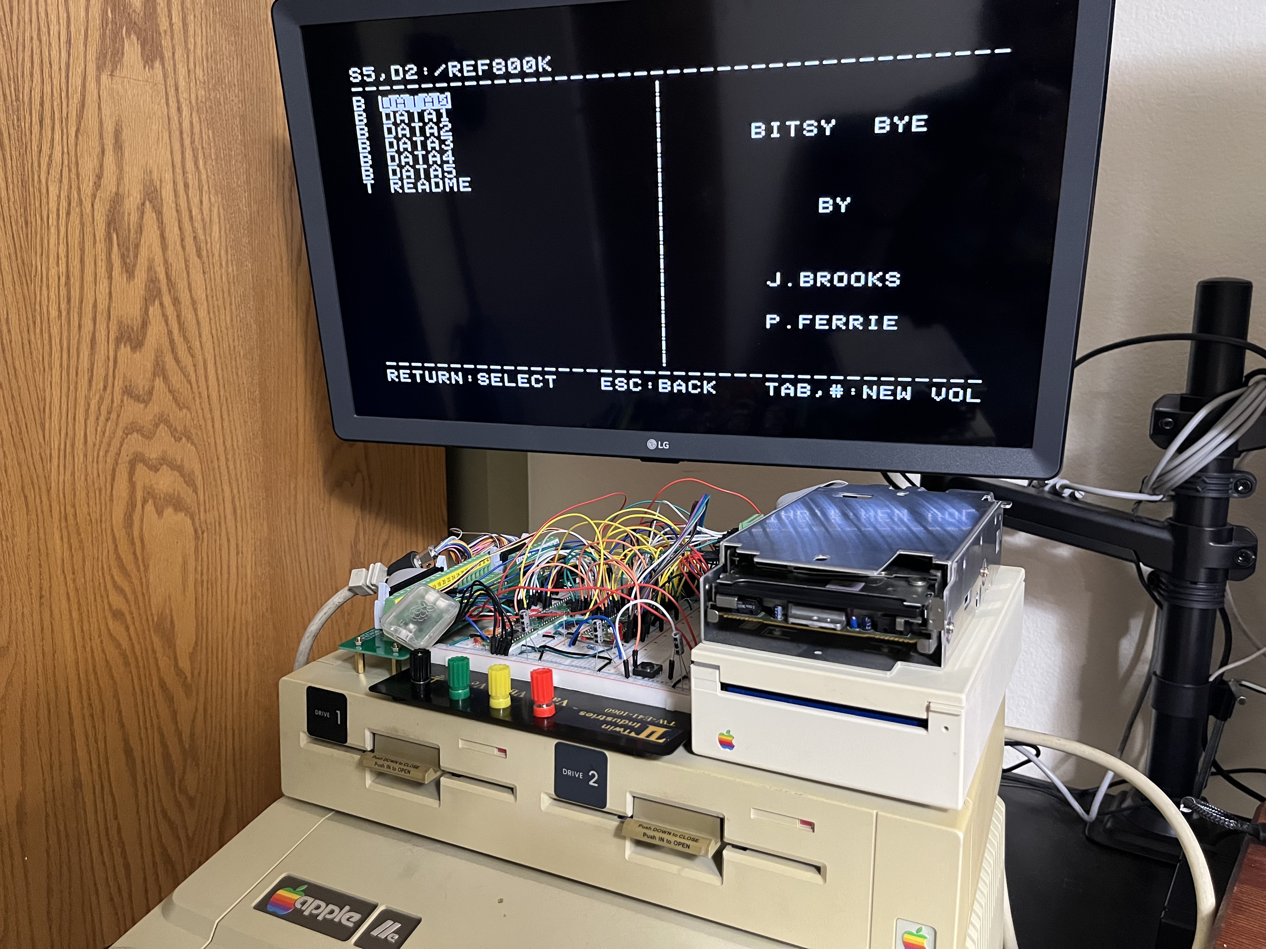
The UniDisk 3.5 is Apple's 800K drive for the Apple II. When its controller board (IF-83, service part 661-0307) dies, there's nothing to fix it with. The board is built around a Sony CXD1013 gate array that has no public datasheet and no replacement, and the only spare board on eBay has sat unsold at $150 for months.
This project replaces the whole board. A Raspberry Pi RP2350 speaks SmartPort to the Apple IIe through the Liron card and drives the stock Sony 800K mechanism directly through its 20-pin connector. The 65C02, ROM, RAM, IWM and the CXD1013 are all gone. The mechanism, the case and the front panel stay.
It isn't a clone of the original. The firmware is new C on the Pico SDK. The original drive ROM is used as a test oracle for SmartPort behavior, status codes, errors and timing, never as a template.
Apple IIe with 800K double-sided ProDOS disks. Macintosh disks (524-byte blocks, Mac interleave) and 400K single-sided disks show up in Apple's docs and the drive ROM but were never used on the IIe, so they're out of scope.
| Parameter | Value |
|---|---|
| MCU | RP2350A on a Raspberry Pi Pico 2 (prototype) |
| Level shifting | 5x SN74LVC8T245, 3.3V to 5V, one DIR and /OE per 8 channels |
| GPIO | 25 of 26 used |
| Host interface | SmartPort, Liron card DB-19 (CN102) |
| Mechanism interface | Sony 800K 20-pin (CN104, ERS 699-0321) |
| Mechanism | Stock Sony 800K double-sided, CX23077A logic + CX20185 read/write amp |
| Rear port | DB-19 daisy chain: PH3_OUT, ENBL_OUT, LASTONE/ |
| Power | +5V and +12V from the host connector; Pico VSYS from +5V through a diode |
 Apple IIe / Liron card                                  Sony 800K mechanism
         | DB-19                                                | 20-pin
   [level shifters]                                    [level shifters]
         |                                                      |
   PIO0: SmartPort FM rx/tx                     PIO1: flux capture / GCR write
   PIO2: rear-port pass-through                                 |
         |                                                      |
   CORE 0: SmartPort device  <---- block request queue ---->  CORE 1: mechanism
   - bus phases, packets                                      - status, seek, motor, eject
   - commands, DIB, status                                    - speed zones
   - daisy-chain ID, LASTONE/                                 - whole-track buffer
                                                              - GCR decode/encode
Each SmartPort read, write or format becomes a request to core 1. Core 0 holds ACK until the answer is back, and the Liron card waits.
Perfboard prototype: done (October 2026). Milestones M0 to M9 passed on the bench with a Pico 2, five 8T245 breakout boards and a mechanism from a dead UniDisk.
| Milestone | What | Log |
|---|---|---|
| M0 | Bench rig, power, shifter boot safety | m0 |
| M1 | Mechanism status reads | m1 |
| M2 | Mechanism commands: motor, seek, eject | m2 |
| M3 | Raw flux capture, decoded on the Mac | m3 |
| M4 | Whole disk read on the board | m4 |
| M5 | Write and format; the working UniDisk reads our disk | m5 |
| M6 | SmartPort on the RP2350; ProDOS boots from a RAM disk | m6 |
| M7 | ProDOS boots from a real floppy through the Liron card | m7 |
| M7.5 | Bench supply retired; runs on the IIe rails | m7_5 |
| M8 | Daisy chain with a working UniDisk, both orders | m8 |
| M9 | Disk swaps, write-protect, ejects, resets, long runs | m9 |
Drop-in PCB: in design. The outline matches the IF-83 and fits the original mounting holes and case opening (checked with 3D prints). The board must stay hand-solderable and well under the $150 the spare board couldn't sell for. Requirements carried from the bench: FABRICATION.md.
Build notes and photos are also on bytehamr.com.
a2m2053_controller/
├── firmware/            # RP2350 firmware (C, Pico SDK)
│   ├── src/             # SmartPort, mechanism server, PIO programs, console
│   └── test/            # Host-side unit tests (fake drive, simulated Liron card)
├── tools/
│   ├── a2m/             # Python: console client, flux decode, GCR, PIO model
│   ├── apple/           # Test disk builders and SPCOMPARE (Applesoft)
│   └── tests/           # pytest
├── hardware/kicad/      # KiCad schematic and PCB
├── docs/
│   ├── build_log/       # Per-milestone notes and measurements
│   ├── captures/        # Scope shots, Apple screens, console logs
│   ├── photos/          # Bench photos
│   ├── superpowers/specs/  # Design spec
│   ├── research_notes.md   # Facts with sources; start here
│   ├── level_shifting.md   # Signal directions and shifter grouping
│   └── pin_budget.md       # GPIO map
└── FABRICATION.md # PCB requirements and part choicestools/requirements.txt)cd firmware
make # build
make test # host-side unit tests
make flash # program over SWD (OpenOCD)
make reset # reset the targetTool paths live in .env.local at the repo root, git-ignored. Copy
.env.example, fill in PICO_SDK_PATH and, if they are not on your PATH,
OPENOCD and GDB. Anything already in your environment or on the make
command line wins over the file. The test-disk scripts in tools/apple/ read
AC_JAR and PRODOS_SRC from the same file.
The firmware exposes a USB CDC console. help lists the commands: mechanism
status and control, flux capture, block reads and writes, whole-disk scans,
format, and sp for the SmartPort bus state and counters. The Python tool
drives the console for the scripted jobs:
cd tools
python -m a2m.cli readdisk --port /dev/cu.usbmodemXXXX --out disk.po --compare ref.poThis project builds on:
Datasheets, Apple and Sony documents, and photos of other people's boards were used during the work but aren't ours to host, so they're not in this repo. docs/SOURCES.md says where each one came from.
This project is released under the MIT License.
Robert Rico
| Qty | Value | Footprint | References |
|---|---|---|---|
| 15 | 10k | Resistor_SMD:R_1206_3216Metric | R1, R2, R3, R4, R5, R6, R7, R8, R9, R11, R12, R13, R14, R15, R18 |
| 10 | 100nF | Capacitor_SMD:C_0805_2012Metric | C1, C2, C3, C4, C5, C6, C7, C8, C9, C10 |
| 5 | SN74LVC8T245DWR | Package_SO:SOIC-24W_7.5x15.4mm_P1.27mm | U1, U2, U3, U4, U5 |
| 3 | 4.7uF 50V | Capacitor_THT:CP_Radial_D5.0mm_P2.00mm | C11, C12, C13 |
| 1 | 100k | Resistor_SMD:R_1206_3216Metric | R10 |
| 1 | 180 | Resistor_SMD:R_1206_3216Metric | R17 |
| 1 | 2k | Resistor_SMD:R_1206_3216Metric | R16 |
| 1 | CN102 host (FROM HOST) | Connector_IDC:IDC-Header_2x10_P2.54mm_Vertical | J3 |
| 1 | CN104 mechanism | Connector_IDC:IDC-Header_2x10_P2.54mm_Vertical | J2 |
| 1 | DB-19 female R/A (daisy chain) | a2m2053:DSUB-19_Female_Horizontal_P2.77x2.84mm_MountingHoles38.8mm | J1 |
| 1 | Eject button | a2m2053:TE_AMP_CT_1x03_P2.00mm_Vertical | J4 |
| 1 | In-use LED | a2m2053:TE_AMP_CT_1x02_P2.00mm_Vertical | J5 |
| 1 | LOGO | a2m2053:logo_sm | G*** |
| 1 | M3 frame ground | a2m2053:MountingHole_3.2mm_M3_Pad_5.2mm | H1 |
| 1 | M3 frame ground | MountingHole:MountingHole_3.2mm_M3_Pad_Via | H2 |
| 1 | Pico 2 | Module:RaspberryPi_Pico_SMD_HandSolder | A1 |
| 1 | STPS2L40AF | Diode_SMD:D_SMA | D1 |
It measures 100 × 110 mm and has 2 copper layers, 1.6 mm thick.
46 parts, built around the STPS2L40AF. The full list of its parts is on this page, with links to each part's symbol and footprint where PCBKit's library has them.
From the robertrico/a2m2053_controller repository on GitHub, at the commit this page was made from: the board is hardware/kicad/a2m2053.kicad_pcb and its schematic hardware/kicad/a2m2053.kicad_sch. PCBKit opens the board in the browser, with nothing to install.
Its repository states no licence, so its author keeps all rights: ask robertrico before reusing the design.

Fabmicro-LLC/Karnix_ASB-254
Karnaugh Interactive Extendable ASIC Simulation Board AKA Karnix ASB-254

robertrico/project_byte_hamr
Open source expansion platform for Apple IIe prototyping and development


github-linguist/linguist
Language Savant. If your repository's language is being reported incorrectly, send us a pull request!

byrantech/laptop
anyon_e, a highly integrated, high end, open source laptop. Attempt the impossible.

VoronDesign/Voron-Hardware
Cool Hardware designed by the Voron Design group
