2 layers72.4 × 42.4 mm
Work
Heartland-Data/esp32-mintia-sensor-kit
本リポジトリは、MINTIAケースにESP32と各種センサを組み込む試作用ファームウェアの参考実装です。
71 parts1Apache-2.0

 rniwase/sdtv2csi55
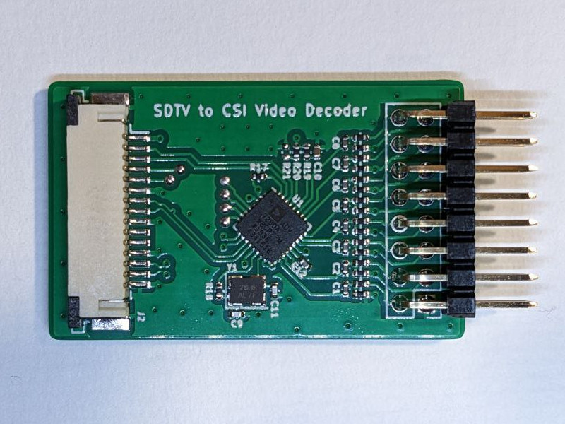
Board for converting SDTV analog video to MIPI CSI-2 using Analog Devices ADV7280A-M.
Sdtv2csi is an open-source printed circuit board by rniwase, from the rniwase/sdtv2csi repository on GitHub, published under the CC0-1.0 licence. It is a 2-layer board of 25 × 40 mm with 67 parts on 55 nets, routed with 334 tracks and 65 vias.
It is built around the NJM12888F18-TE1 and ABM8G-28.63636MHZ-4Y. Its parts include 30 capacitors, 21 resistors, 2 ICs, 2 connectors and 1 crystal.


Board for converting SDTV analog video to MIPI CSI-2 using Analog Devices ADV7280A-M.
wget https://github.com/rniwase/sdtv2csi/raw/master/rpi/install_patch.sh
sudo bash install_patch.sh# for Raspberry Pi OS Bookworm:
sudo bash -c 'echo "dtoverlay=adv728x-m,adv7280m=1" >> /boot/firmware/config.txt'
# for Raspberry Pi OS Bullseye:
sudo bash -c 'echo "dtoverlay=adv728x-m,adv7280m=1" >> /boot/config.txt'sudo reboot
sudo v4l2-ctl --all -d /dev/video0Connect NTSC composite video signal to VIDEO_IN pin header AIN1-GND
Install FFmpeg
sudo apt update
sudo apt install ffmpeg# Record full video including blanking line
ffmpeg -an -video_size 720x507 -r 29.97 -i /dev/video0 -c:v rawvideo -vf realtime -t 5 out.asf
# Record video with blanking lines cropped
ffmpeg -an -video_size 720x507 -r 29.97 -i /dev/video0 -c:v rawvideo -vf realtime,crop=720:480:0:27 -t 5 out_crop.asf| Qty | Value | Footprint | References |
|---|---|---|---|
| 14 | 0.1μF | Capacitor_SMD:C_0402_1005Metric | C1, C2, C3, C4, C5, C6, C7, C8, C12, C21, C22, C23, C24, C25 |
| 8 | 24Ω | Resistor_SMD:R_0402_1005Metric | R1, R2, R3, R4, R5, R6, R7, R8 |
| 8 | 51Ω | Resistor_SMD:R_0402_1005Metric | R9, R10, R11, R12, R13, R14, R15, R16 |
| 6 | 10nF | Capacitor_SMD:C_0402_1005Metric | C14, C26, C27, C28, C29, C30 |
| 6 | TestPoint | TestPoint:TestPoint_Pad_D1.0mm | TP1, TP2, TP3, TP4, TP5, TP6 |
| 5 | 10μF | Capacitor_SMD:C_0402_1005Metric | C16, C17, C18, C19, C20 |
| 5 | 600Ω | Inductor_SMD:L_0603_1608Metric | FB1, FB2, FB3, FB4, FB5 |
| 3 | 4.7kΩ | Resistor_SMD:R_0402_1005Metric | R17, R19, R20 |
| 2 | 20pF | Capacitor_SMD:C_0402_1005Metric | C9, C11 |
| 1 | 100μF | Capacitor_SMD:C_1206_3216Metric | C13 |
| 1 | 4.7μF | Capacitor_SMD:C_0402_1005Metric | C10 |
| 1 | 47μF | Capacitor_SMD:C_1206_3216Metric | C15 |
| 1 | 560Ω | Resistor_SMD:R_0402_1005Metric | R18 |
| 1 | ABM8G-28.63636MHZ | Crystal:Crystal_SMD_3225-4Pin_3.2x2.5mm | Y1 |
| 1 | ADV7280A-M | Package_CSP:LFCSP-32-1EP_5x5mm_P0.5mm_EP3.25x3.25mm | U1 |
| 1 | DNP | Resistor_SMD:R_0402_1005Metric | R21 |
| 1 | NJM12888F18 | Package_TO_SOT_SMD:SOT-23-5 | U2 |
| 1 | RPI_CSI_TOP | Connector_FFC-FPC:TE_1-84953-5_1x15-1MP_P1.0mm_Horizontal | J2 |
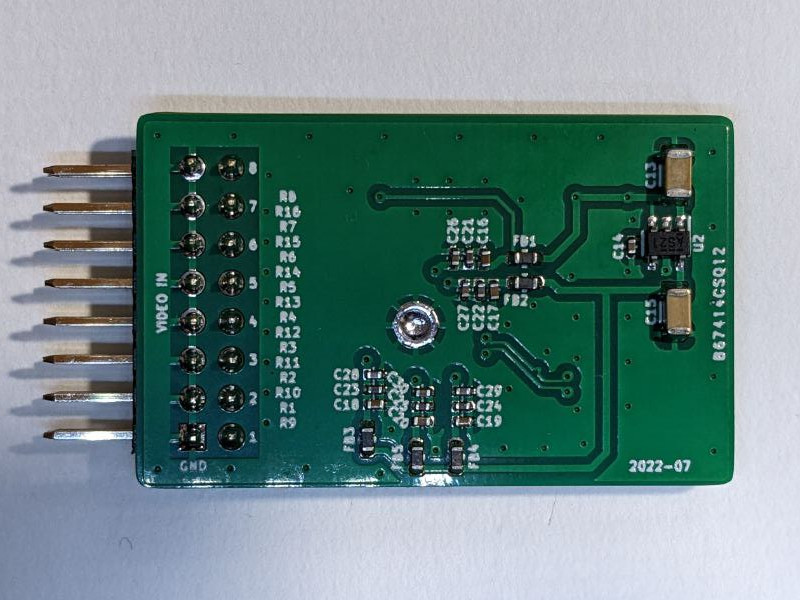
| 1 | VIDEO_IN | Connector_PinHeader_2.54mm:PinHeader_2x08_P2.54mm_Vertical | J1 |
Heartland-Data/esp32-mintia-sensor-kit
本リポジトリは、MINTIAケースにESP32と各種センサを組み込む試作用ファームウェアの参考実装です。


Ardumower/ardumower
Develop an open source robotic lawn mower (HW+SW reference platform)

CRImier/MyKiCad
My KiCad boards. Can't be bothered uploading individually anymore, so here you go.


It measures 25 × 40 mm and has 2 copper layers, 0.8 mm thick.
67 parts, built around the NJM12888F18-TE1 and ABM8G-28.63636MHZ-4Y. The full list of its parts is on this page, with links to each part's symbol and footprint where PCBKit's library has them.
From the rniwase/sdtv2csi repository on GitHub, at the commit this page was made from: the board is pcb/sdtv2csi.kicad_pcb and its schematic pcb/sdtv2csi.kicad_sch. PCBKit opens the board in the browser, with nothing to install.
Its repository publishes it under the CC0-1.0 licence: you may reuse it on that licence's terms (keep the author's notice, and for a copyleft licence share your changes alike).