4 layers195.5 × 114.3 mm

 rmskkn/fanny
USB 4ch PC fan controller
Fan controller is an open-source printed circuit board by rmskkn, from the rmskkn/fanny repository on GitHub. It is a 2-layer board of 81 × 78 mm with 97 parts on 85 nets, routed with 783 tracks and 74 vias.
It is built around the BSS138, AO3401A and BAT54S, with the SS34 and SMBJ13A among its other parts. Its parts include 42 resistors, 20 transistors, 11 connectors, 9 capacitors and 9 diodes.


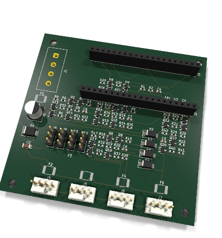
A USB-controlled carrier board for an STM32F103C8T6 "Blue Pill" module. It
drives four 12 V PC fans and reads four analog sensors. The module shows up
on the host as a USB CDC serial port (/dev/ttyACM* or COMx).
pwm (4-pin
signal control) and dc (3-pin supply chopping) at runtime.fanctl.py) and
a daemon (fancontrold.py) for temperature or GPU-temperature curves..
├── firmware/ MCU firmware
│ ├── Core/ clocks, SysTick, linker script, board pin map
│ ├── Drivers/ libopencm3 submodule
│ ├── USB_DEVICE/ USB CDC-ACM device
│ ├── App/ fan, pwm, tach, protocol, thermal, safety
│ └── tests/ host-side unit tests
├── hardware/
│ ├── kicad/ schematic, symbol lib, board
│ ├── bom.csv bill of materials
│ ├── pcb_3d.png 3D render of the placed board
│ ├── pcb_top.png placement plot seen from the top
│ └── datasheets/ links to the key datasheets
└── host/ fanctl.py command-line client (pyserial)KiCad 10.0.7, arm-none-eabi-gcc, OpenOCD, and Python 3 with pyserial:
# Arch
sudo pacman -S kicad arm-none-eabi-gcc arm-none-eabi-newlib openocd python python-pyserial

# Ubuntu 24.04
sudo add-apt-repository ppa:kicad/kicad-10.0-releases
sudo apt update
sudo apt install kicad gcc-arm-none-eabi openocd python3 python3-serial
You also need an ST-Link V2 programmer wired to the Blue Pill's SWD header to flash firmware.
flowchart LR
    classDef power fill:#fde3d8,stroke:#e2572b,color:#111
    classDef usb fill:#dbe7ff,stroke:#2f6fed,color:#111
    classDef mcu fill:#e8d7f5,stroke:#5b4b8a,color:#111
    classDef pwm fill:#d7f5df,stroke:#2f9e44,color:#111
    classDef dcmode fill:#fdecc3,stroke:#c77f00,color:#111
    classDef tach fill:#d7f5df,stroke:#0f9b8e,color:#111
    classDef analog fill:#fbd9e8,stroke:#c2255c,color:#111

    subgraph PWR["Power 12 V"]
        PSU["12 V PSU"] --> J1["J1 Mate-N-Lok"] --> F1["F1 PTC 2.5A"] --> D1["D1 TVS"] --> V12["+12V"]
        V12 --> F25["F2..F5 1.1A PTC x4"] --> FANV["fan +12V x4"]
        V12 --> DIV["47k/10k divider"] --> PB0["PB0 ADC"]
    end

    subgraph USB3V3["USB / 3V3"]
        USB["USB via Blue Pill microB"] --> P5V["+5V"] --> LDO["Blue Pill LDO"] --> V33["+3V3"] --> FB1["FB1"] --> V33A["+3V3A"]
    end

    subgraph MCU["Blue Pill module on J2 and J3"]
        subgraph PWMSIG["PWM signal on fan pin 4"]
            TIM4["TIM4 PB6..PB9 25kHz"] --> BSS["BSS138 open drain"] --> FPWM["fan PWM pin"]
        end
subgraph DCMODE["DC-mode motor switch per channel"]| Function | Pins | Peripheral |
|---|---|---|
| Fan 1–4 PWM signal and the motor-switch chop signal in DC mode | PB6 PB7 PB8 PB9 | TIM4 CH1–4 at 25 kHz |
| Fan 1–4 DC-mode enable | PA6 PA7 PA8 PB1 | plain push-pull GPIO |
| Fan 1–4 tach | PB12–PB15 | EXTI12–15 on the falling edge |
| AIN1–AIN4 | PA0–PA3 | ADC1 IN0–IN3 |
| 12 V sense | PB0 | ADC1 IN8 |
Verified against the Intel 4-wire PWM fan spec rev 1.2:
| Spec requirement | Board implementation | Status |
|---|---|---|
| Pinout of GND then +12 V then tach then PWM | Fan_4pin header wired in that order | Match |
| PWM must be open-drain or open-collector with the fan pulling up | BSS138 open-drain transistor where the MCU only sinks | Match |
| PWM frequency between 21 kHz and 28 kHz with 25 kHz nominal | TIM4 at 72 MHz / 2880 which is exactly 25.000 kHz | Match |
| A released PWM line must run the fan at full speed | 100 kΩ pull-down holds the transistor off until firmware drives it | Match |
| Tach must be open-collector and pulled up at 2 pulses per rev | 10 kΩ pull-up to 3.3 V with TACH_PULSES_PER_REV = 2 in firmware | Match |
| Tach pull-up rail of 5 V or less into a tolerant input | Pulled to 3.3 V and PB12–PB15 are 5 V tolerant | Match |
Each input is a 3-pin header carrying 3V3A and SIG and GND. The conditioning chain works like this:
The ADC references VDDA. The firmware measures VREFINT so it can report millivolts corrected for the actual supply voltage.
The full bill of materials is in hardware/bom.csv.
git clone --recurse-submodules git@github.com:rmskkn/fanny.git
cd fanny
make                 # firmware/build/fanny.elf, .bin (~11.5 KiB flash)
make flash           # flash fanny.bin, OpenOCD + ST-Link over SWD
make test            # host-side protocol and conversion tests
The first make builds libopencm3 for STM32F1 only. It also runs
git submodule update --init when the clone has no submodule checkout. The
same targets work from inside firmware/.
make flash wraps this OpenOCD call, with an ST-Link programmer on the
Blue Pill's SWD header. fanny.bin is a raw image with no load address, so
one is given on the command line, the start of flash on this MCU:
openocd -f interface/stlink.cfg -f target/stm32f1x.cfg \
    -c "program firmware/build/fanny.bin verify reset exit 0x08000000"
fanny.elf still builds alongside it (make keeps producing both), kept
for arm-none-eabi-size and debugging, but flashing only ever needs the bin.
All fans run at 100 % whenever the controller is not in control and that holds
in both pwm and dc mode. Fan power comes straight from 12 V so this needs
nothing but 12 V present. The PWM signal line and the motor switch and the
DC-mode enable all rest in their "fan on" state. Pin 4 is released and
R_gpd holds the motor switch on and R_dcen holds the enable off. Either
mode reaches 100 % the same way.
| Case | Result |
|---|---|
| Power-up before the first command from the host | 100 % |
| USB unplugged or host powered off | Module unpowered and both switches rest on at 100 % |
| Module pulled out of its socket | Both switches rest on at 100 % |
| Supply sags below the reset threshold of the STM32 near 1.9 V | MCU held in reset and both switches rest on at 100 % |
| Firmware hangs | Watchdog resets the MCU after 1 s and both switches rest on during reset at 100 % |
| No valid command for 10 s while the module is still powered | Firmware failsafe sets 100 % and the LED blinks fast and the mode stays unchanged |
Running fanctl.py watch or a control daemon keeps the 10 s timer from
expiring. A fan is flagged stall=1 when its duty sits above 0 but its tach
reads 0 RPM for 3 s. Fans without a tach wire always show this flag.
The protocol is text over USB CDC and the baud rate is ignored. Each command
is one line ending in \n and each reply ends with ok or err <reason>.
> set 2 40          duty 0..100 for fan 1..4 or "all"
ok
> mode 3 dc         pwm (4-pin) | dc (3-pin)
ok
> get
fan 1 mode=pwm duty=100 rpm=1590 stall=0
fan 2 mode=pwm duty=40 rpm=780 stall=0
fan 3 mode=dc duty=100 rpm=1200 stall=0
fan 4 mode=pwm duty=100 rpm=0 stall=1
ain 1 raw=2047 mv=1649
...
v12 mv=12043
vdda mv=3302
mcu temp=31.4
failsafe=0
ok
> ping              keepalive
okpip install -r host/requirements.txt
python3 host/fanctl.py -p /dev/ttyACM0 get
python3 host/fanctl.py set all 50
python3 host/fanctl.py mode 3 dc
python3 host/fanctl.py watch -i 2Use the fan number from 1 to 4 in place of all. Fan 1 is header J5 and fan
4 is header J8.
python3 host/fanctl.py set 1 50      # fan 1 to 50 %
python3 host/fanctl.py set 3 80      # fan 3 to 80 %
python3 host/fanctl.py set 4 0       # fan 4 to 0 % (some fans keep turning slowly)
python3 host/fanctl.py -p /dev/ttyACM1 set 2 40 # board on another port1,2 and ranges such
as 1-3 are not accepted.python3 host/fanctl.py get and read the
fan N mode=... duty=... rpm=... line.fanctl.py watch
or a control daemon running to hold the values.mode <1-4|all> pwm|dc picks the speed-control path for a channel: pwm
for a 4-pin fan, dc for a 3-pin fan. It falls back to pwm at every
boot and after every reconnect so the channel of a 3-pin fan needs
mode N dc sent again each time.The FanController class in fanctl.py can be imported to build a control
daemon. One example is a daemon that maps an NTC reading from ain onto a fan
duty. For a 10 kΩ NTC sitting on the 10 kΩ bias resistor the resistance is
RNTC = 10 kΩ × mV / (VDDA − mV).
host/fancontrold.py is exactly that daemon. It reads an INI config shown in
host/fancontrol.conf.example. The config can set each of the four channels
to a constant duty or to a temperature curve driven by one AIN input or to a
curve driven by the temperature of an NVIDIA GPU through sensor = gpuN read
via nvidia-smi using the higher of the core and memory temperature. A
managed channel also takes type = pwm for the 4-pin default or type = dc
for a 3-pin fan. The daemon sends mode once at startup and again after every
reconnect because a firmware reset returns every channel to pwm. Every cycle
it re-sends the duty of each managed channel which doubles as the ping that
holds off the 10 s firmware failsafe. A channel with no [fanN] section is
left alone. nvidia-smi must be on PATH and no extra Python dependency is
needed.
For a gpuN sensor install the proprietary NVIDIA driver which provides
nvidia-smi:
# Arch
sudo pacman -S nvidia nvidia-utils

# Ubuntu 24.04
sudo apt install nvidia-driver-550
Reboot the machine to load the nvidia modules. Verify with
nvidia-smi --query-gpu=index,temperature.gpu,temperature.memory --format=csv.
cp host/fancontrol.conf.example ~/.config/fancontrol.conf
# edit ~/.config/fancontrol.conf for your sensors and curves
python3 host/fancontrold.py                 # foreground, Ctrl-C to stop
To run it as a systemd user service:
mkdir -p ~/.config/systemd/user
cp host/systemd/fancontrold.service ~/.config/systemd/user/
# edit ExecStart in that file to this repo's checkout path
systemctl --user daemon-reload
systemctl --user enable --now fancontrold.service
loginctl enable-linger "$USER" # only if the board must run with no user session logged inpwm mode (fan-dependent). It does
stop the fan in dc mode.dc mode won't start below ~30-40 % duty (motor limit,
not firmware). Set a curve minimum above it.dc mode since the fan is unpowered during the
chopped-off phase. stall is only meaningful near 100 % duty.pwm channels share one chop frequency.Copyright © 2026 Roman Skakun.
This project covers the hardware design files and the firmware and the host tool. All of it is licensed under Creative Commons Attribution-NonCommercial-ShareAlike 4.0 International which is CC BY-NC-SA 4.0.
You may build and modify and share this design for personal and other non-commercial purposes with attribution and under the same license. Commercial use is not permitted without a separate written license from the copyright holder. That includes selling assembled boards or bare PCBs or kits.
firmware/Drivers/libopencm3 is a submodule under its own LGPL-3.0 license
and is not covered by the above.
| Qty | Value | Footprint | References |
|---|---|---|---|
| 13 | 10k | Resistor_SMD:R_0603_1608Metric | R2, R7, R13, R19, R25, R32, R33, R35, R36, R38, R39, R41, R42 |
| 12 | BSS138 | Package_TO_SOT_SMD:SOT-23 | Q2, Q3, Q5, Q6, Q8, Q9, Q11, Q12, Q13, Q15, Q17, Q19 |
| 8 | 100 | Resistor_SMD:R_0603_1608Metric | R3, R5, R9, R11, R15, R17, R21, R23 |
| 8 | 1k | Resistor_SMD:R_0603_1608Metric | R8, R14, R20, R26, R27, R28, R29, R30 |
| 8 | AO3401A | Package_TO_SOT_SMD:SOT-23 | Q1, Q4, Q7, Q10, Q14, Q16, Q18, Q20 |
| 4 | 1.1A | Fuse:Fuse_1812_4532Metric | F2, F3, F4, F5 |
| 4 | 100k | Resistor_SMD:R_0603_1608Metric | R6, R12, R18, R24 |
| 4 | 1n | Capacitor_SMD:C_0603_1608Metric | C6, C7, C8, C9 |
| 4 | 2.2k | Resistor_SMD:R_0603_1608Metric | R4, R10, R16, R22 |
| 4 | 4.7k | Resistor_SMD:R_0603_1608Metric | R31, R34, R37, R40 |
| 4 | BAT54S | Package_TO_SOT_SMD:SOT-23 | D6, D8, D9, D10 |
| 4 | SS34 | Diode_SMD:D_SMA | D2, D3, D4, D5 |
| 1 | 100n | Capacitor_SMD:C_0603_1608Metric | C4 |
| 1 | 100u 25V | Capacitor_SMD:CP_Elec_6.3x7.7 | C1 |
| 1 | 10n | Capacitor_SMD:C_0603_1608Metric | C5 |
| 1 | 10u 25V | Capacitor_SMD:C_1206_3216Metric | C2 |
| 1 | 12V IN | fanctl:ConnHeader_MateNLok_1x04_P5.08mm_Vertical | J1 |
| 1 | 1u | Capacitor_SMD:C_0603_1608Metric | C3 |
| 1 | 2.5A | Fuse:Fuse_1812_4532Metric | F1 |
| 1 | 47k | Resistor_SMD:R_0603_1608Metric | R1 |
| 1 | 600R@100MHz | Inductor_SMD:L_0603_1608Metric | FB1 |
| 1 | AIN1 | Connector_PinHeader_2.54mm:PinHeader_1x03_P2.54mm_Vertical | J11 |
| 1 | AIN2 | Connector_PinHeader_2.54mm:PinHeader_1x03_P2.54mm_Vertical | J8 |
| 1 | AIN3 | Connector_PinHeader_2.54mm:PinHeader_1x03_P2.54mm_Vertical | J9 |
| 1 | AIN4 | Connector_PinHeader_2.54mm:PinHeader_1x03_P2.54mm_Vertical | J10 |
| 1 | BluePill A | Connector_PinSocket_2.54mm:PinSocket_1x20_P2.54mm_Vertical | J2 |
| 1 | BluePill B | Connector_PinSocket_2.54mm:PinSocket_1x20_P2.54mm_Vertical | J3 |
| 1 | FAN1 | Connector:FanPinHeader_1x04_P2.54mm_Vertical | J4 |
| 1 | FAN2 | Connector:FanPinHeader_1x04_P2.54mm_Vertical | J5 |
| 1 | FAN3 | Connector:FanPinHeader_1x04_P2.54mm_Vertical | J6 |
| 1 | FAN4 | Connector:FanPinHeader_1x04_P2.54mm_Vertical | J7 |
| 1 | SMBJ13A | Diode_SMD:D_SMB | D1 |

The-Hybrid-Atelier/RheoBoard
RheoBoard is open hardware for pneumatic retraction-extrusion measurements.


dephekt/dosing-pump-hardware
Open schematics and design files for a computer controlled nutrient dosing system

Eight4aWish/eurorack_electronics
Analogue designs and breadboard layouts: the Dual Pingable LPG, and the board behind Boy.

Momozavur/Mravka-v3
Open the appropriate .kicadpro file in KiCad; .pro entries are legacy projects. Keep schematics, boards, local libraries, library tables, and supporting files together.

AssaadMH/shadow-4wd-motor-shield-pcb
The 24-signal interface board that replaces SHADOW's perfboard wiring — and the two pin conflicts that only appeared on re-checking the spec.

It measures 81 × 78 mm and has 2 copper layers, 1.6 mm thick.
97 parts, built around the BSS138, AO3401A, BAT54S and SS34. The full list of its parts is on this page, with links to each part's symbol and footprint where PCBKit's library has them.
From the rmskkn/fanny repository on GitHub, at the commit this page was made from: the board is hardware/kicad/fan_controller.kicad_pcb and its schematic hardware/kicad/fan_controller.kicad_sch. PCBKit opens the board in the browser, with nothing to install.
Its repository states no licence, so its author keeps all rights: ask rmskkn before reusing the design.