Skip to the content
PCBKitNew board
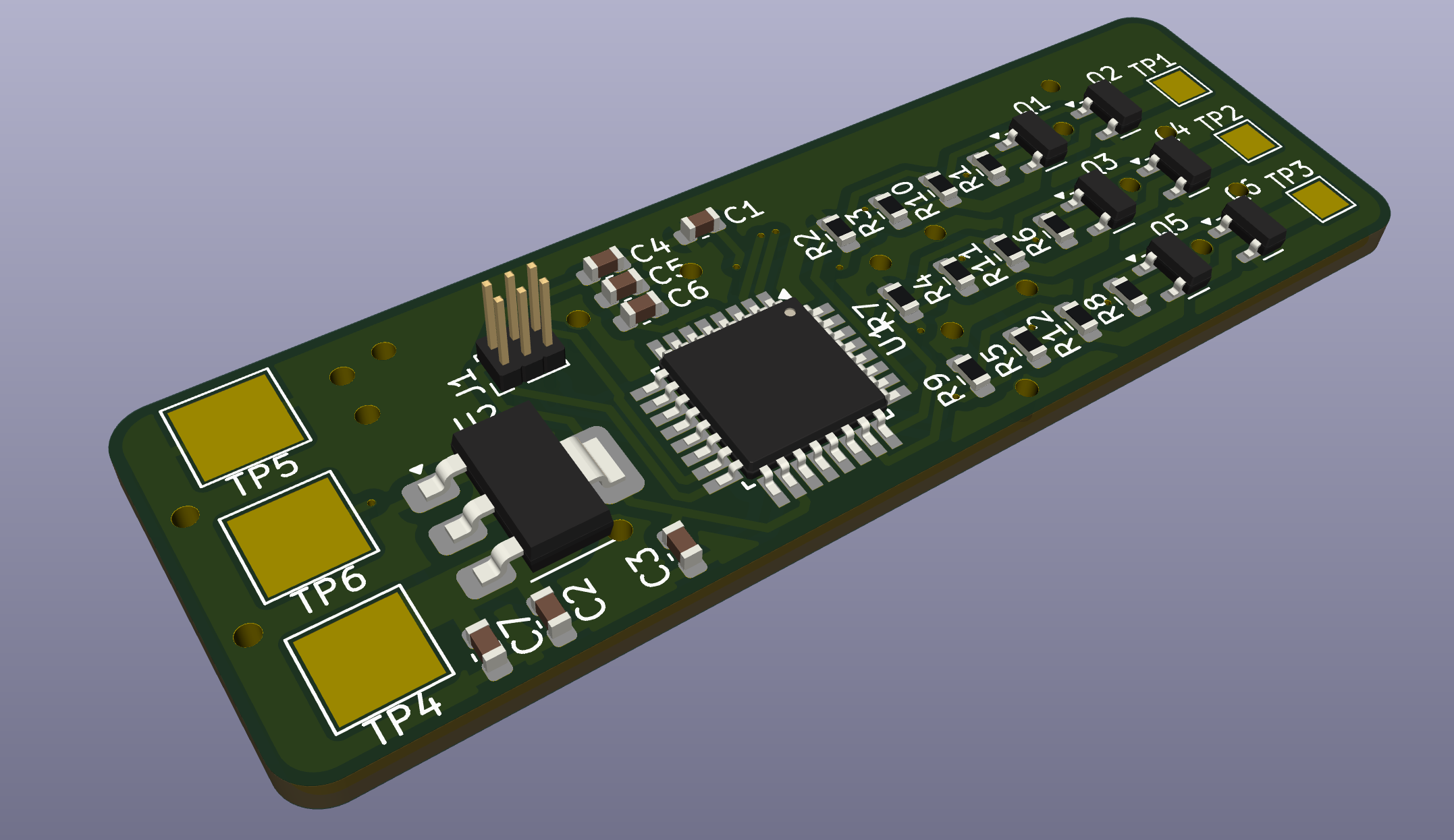
2 layers56.8 × 19 mmOpen esc, the printed circuit board in 3D

Open-Source 3-Phase Sensorless ESC Firmware

Size
56.8 × 19 mm
Copper layers
2
Thickness
1.6 mm
Parts
34
Nets
33
Pads
104
Tracks, vias
225, 41
Pours
1
Routed
Yes
KiCad
KiCad 8.0 (file 20240108)
Created
13 May 2025
Updated
17 May 2025

Overview

Open esc is an open-source printed circuit board by rmingon, from the rmingon/open-esc repository on GitHub. It is a 2-layer board of 56.8 × 19 mm with 34 parts on 33 nets, routed with 225 tracks and 41 vias.

It is built around the ATMEGA88PA-AU, AMS1117-3.3 and AO3401A, with the IRLML0030 among its other parts. Its parts include 12 resistors, 7 capacitors, 6 transistors, 2 ICs and 1 connector. It belongs with the robots and motor control boards and the AVR (ATmega, ATtiny) boards of this library.

Main components

4

README

README.md

Open-Source 3-Phase Sensorless ESC Firmware

This is an open-source firmware for controlling 3-phase sensorless BLDC motors using an ATmega88PA microcontroller running at 8 MHz (internal oscillator).
It is designed for small electric vehicles, drones, robotics, and DIY ESC applications.
The design uses 6 MOSFETs in a three-phase bridge configuration and includes back-EMF sensing for sensorless commutation.


Features

  • Sensorless 6-step (trapezoidal) commutation
  • Automatic open-loop startup
  • Zero-cross detection via ADC ISR
  • Hardware timer-based phase PWM with dead-time
  • RC PWM input for speed control
  • Optional serial interface (UART) for speed setting
  • Direction control and braking support
  • Dead-time insertion to prevent MOSFET shoot-through
  • Auto-calibrated ADC thresholds for zero-cross detection

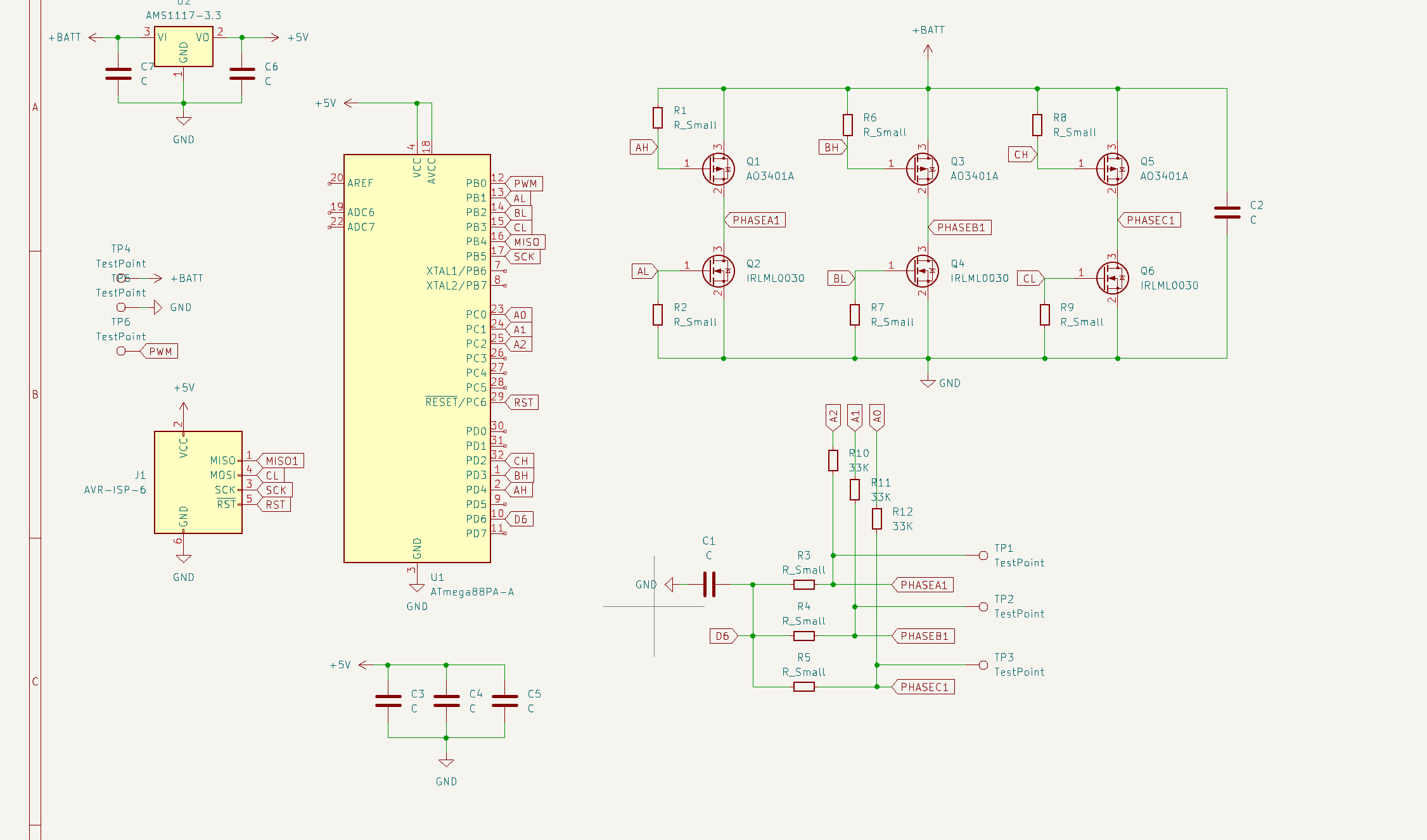
Schematic Overview

The system includes the following main blocks:

Microcontroller

  • ATmega88PA, powered at 5V using AMS1117-3.3 regulator from +BATT
  • Internal 8 MHz oscillator (no external crystal)
  • Key pins used:
    • PD2 → PWM input (from RC receiver)
    • PD3/PD4/PD5 → High-side MOSFET gates (AH, BH, CH)
    • PB0/PB1/PB2 → Low-side PWM outputs (AL, BL, CL)
    • PC0/PC1/PC2 → ADC inputs for Phase A/B/C sensing (A0, A1, A2)

Power Stage

  • 3-phase half-bridge using 6 MOSFETs (Q1–Q6)
  • High-side: A03401A
  • Low-side: IRLML0030
  • Gate resistors to control switching speed and prevent ringing

Back-EMF Sensing

  • Analog divider + DC blocking on each motor phase
  • Inputs go to A0, A1, and A2
  • Used for zero-cross detection in closed-loop mode

PWM Input

  • Connected to D2 for RC signal input (standard 1–2 ms pulses)
  • Used to control speed and direction
  • Interrupt-based decoding for accurate readings

Serial Debug (optional)

  • Via UART (TX/RX, PD0/PD1)
  • Can be used to override speed or monitor state

How to Use

1. Assemble the Hardware

  • Follow the schematic to build the ESC on a PCB or breadboard
  • Ensure proper power filtering (C2, C3–C6)
  • Use heatsinks or airflow on the MOSFETs if under heavy load

2. Upload Firmware

  • Connect AVR ISP programmer to the 6-pin header
  • Use AVRDude or the Arduino IDE
  • Ensure fuse bits are set for:
    • Internal 8 MHz clock
    • No clock division
  • Upload the .ino firmware file

3. Calibrate Zero-Crossing (Auto)

  • When powered, the firmware automatically calibrates ADC offset thresholds
  • Ensure the motor is disconnected or not rotating for accurate calibration

4. Run

  • Connect an RC receiver or PWM generator to D2
  • Pulse width controls speed and direction:
    • < 1480 µs = reverse
    • 1480–1520 µs = brake
    • > 1520 µs = forward
  • Motor will spin up in open-loop mode and switch to sensorless control

5. Serial Control (Optional)

  • Connect USB-to-serial to TX/RX
  • Open serial monitor at 115200 baud
  • Send a value from 0–255 to manually set the speed (for testing/debug)

Motor Braking and Reverse

  • Controlled by PWM signal:
    • Brake mode: both high and low sides turned off briefly
    • Reverse: same commutation order but in reverse
  • No position feedback required

Dead-Time Handling

  • Implemented in software by carefully disabling/enabling high/low MOSFETs with a short delay (a few µs)
  • Prevents simultaneous conduction and shoot-through

Files Included

  • ESC_Firmware.ino – Full firmware with PWM control, ISR ADC, RC interface
  • README.md – Project documentation
  • Schematic (.png) – Visual hardware design

Supported Microcontrollers

  • ATmega88PA (default)
  • Can be ported to ATmega328P with minimal changes

Test Points

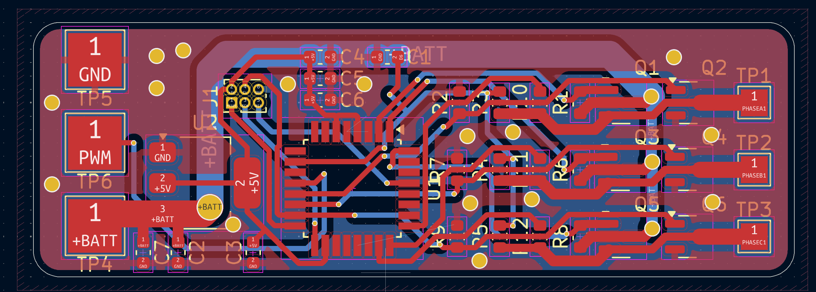
  • TP1–TP3: Phase voltages for probing/debug
  • TP6: PWM input
  • TP5: GND
  • TP4: +BATT

Pictures

3d pcb schematic


Safety Notes

  • Always test with low-voltage supply first
  • Double-check gate drive signals with oscilloscope
  • Use overcurrent and overtemperature protection externally if needed

License

MIT License — You can freely use, modify, and distribute this project.


Author

Created by [Your Name / GitHub Handle]
Feel free to fork, improve, and contribute via pull requests!

Parts

34
QtyValueFootprintReferences
9R_SmallResistor_SMD:R_0603_1608MetricR1, R2, R3, R4, R5, R6, R7, R8, R9
7CCapacitor_SMD:C_0603_1608MetricC1, C2, C3, C4, C5, C6, C7
333KResistor_SMD:R_0603_1608MetricR10, R11, R12
3AO3401APackage_TO_SOT_SMD:SOT-23Q1, Q3, Q5
3IRLML0030Package_TO_SOT_SMD:SOT-23Q2, Q4, Q6
3TestPointTestPoint:TestPoint_Pad_2.0x2.0mmTP1, TP2, TP3
3TestPointTestPoint:TestPoint_Pad_4.0x4.0mmTP4, TP5, TP6
1AMS1117-3.3Package_TO_SOT_SMD:SOT-223-3_TabPin2U2
1ATmega88PA-APackage_QFP:TQFP-32_7x7mm_P0.8mmU1
1AVR-ISP-6Connector_PinHeader_1.00mm:PinHeader_2x03_P1.00mm_VerticalJ1

Questions

How big is the Open esc PCB?

It measures 56.8 × 19 mm and has 2 copper layers, 1.6 mm thick.

What parts does the Open esc use?

34 parts, built around the ATMEGA88PA-AU, AMS1117-3.3, AO3401A and IRLML0030. The full list of its parts is on this page, with links to each part's symbol and footprint where PCBKit's library has them.

Where can I download the Open esc KiCad files?

From the rmingon/open-esc repository on GitHub, at the commit this page was made from: the board is hardware/Open-esc.kicad_pcb and its schematic hardware/Open-esc.kicad_sch. PCBKit opens the board in the browser, with nothing to install.

Can I use the Open esc design in my own project?

Its repository states no licence, so its author keeps all rights: ask rmingon before reusing the design.

Similar boards

  • 2 layers73.8 × 37.3 mmZx tsid, the printed circuit board in 3D

    Zx tsid

    UzixLS/zx-tsid

    MOS SID sound card for ZX Spectrum

    64 parts22MIT
  • 2 layers39.6 × 35.7 mmH bridge dc motor controller, the printed circuit board in 3D

    H bridge dc motor controller

    yendiDev/h-bridge-dc-motor-controller

    This PCB design uses PMOS and NMOS field-effect transistors to control the direction of current flowing to a DC motor.

    14 parts
  • 2 layers80 × 117.3 mmMicromouse pcb, the printed circuit board in 3D

    Micromouse pcb

    jtorbett/micromouse-pcb

    An electronic design for a micromouse

    98 parts1
  • 2 layers89.3 × 55 mmKh gift hw, the printed circuit board in 3D

    Kh gift hw

    phonght32/kh-gift-hw

    69 partsMIT
  • 2 layers162 × 60 mmAir detector, the printed circuit board in 3D

    Air detector

    shm-dmitry/air-detector

    Air status sensor with hass integration and fan control

    132 partsApache-2.0
  • 2 layers100 × 100 mmPower V2 main, the printed circuit board in 3D

    Power V2 main

    ICRS/IPRL-Electronics-Hardware

    61 parts1
  • 2 layers95.8 × 30.5 mmAngelnu esphome pcb power usb, the printed circuit board in 3D

    Angelnu esphome pcb power usb

    punkfab/pcb-corpus

    235 real KiCad boards from open-source hardware repositories, prepared as a placement and routing benchmark

    56 parts1
  • 4 layers97.5 × 52 mmMain module, the printed circuit board in 3D

    Main module

    shm-dmitry/auto_close_window

    This IOT project allows you to open and close your window from any smart house. For example - you can setup rules like a "If night and noise greater then expected -> close window" and "Noise reduced -> open window"

    121 parts1Apache-2.0