
2 layers
LM80C R6
leomil72/LM80C
A Z80-based homebrew computer withTMS9918, AY-3-8910, Z80 CTC, Z80 PIO, and Z80 SIO
153 parts123GPL-3.0

 rixnobis/rj45-mapper
RJ45 cable pin mapper: touch a flying wire to the pad, the LED for its 8P8C pin lights
Rj45-mapper is an open-source printed circuit board by rixnobis, from the rixnobis/rj45-mapper repository on GitHub. It is a 2-layer board of 75 × 50 mm with 29 parts on 30 nets, routed with 75 tracks and 68 vias.
It is built around the ULN2803A. Its parts include 12 resistors, 9 diodes, 2 connectors and 1 IC.
A bench probe for unknown cables that have an 8P8C (RJ45) plug on one end and loose wires on the other. Plug the cable into the jack and touch one loose wire to the pad. The LED for the jack pin that wire lands on lights up. If two pins are shorted together in the cable, two LEDs light.
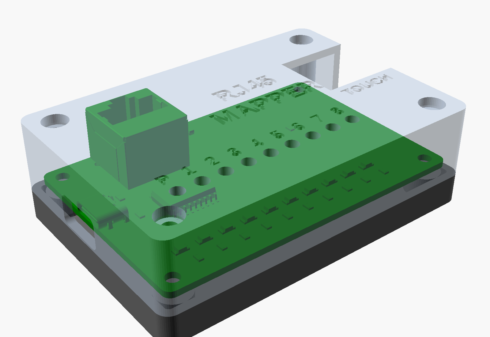
The pad sits at 5 V through 1k. Each jack pin drives one input of a ULN2803A, and each ULN output sinks one red LED through 330R (about 7 mA). A wire grounded at its far end draws 5 mA from the pad, so it is not a short. A finger across the pad and a wire (around 1 Mohm) puts the input under 0.1 V, far below the two-VBE turn-on of the ULN input, so only metal contact lights an LED. Power is USB-C at 5 V, with a separate 5.1k on each CC pin.
JLC assembles everything except the jack: fab/rj45-mapper-bom.csv and
fab/rj45-mapper-cpl.csv. The jack is any unshielded right-angle 8P8C on the TE
5555164 / Amphenol 54602 land pattern (8 x 0.89 mm on 1.27 mm pitch, rows 2.54 mm
apart, 3.25 mm pegs 11.43 mm apart), bought separately and hand-soldered; see
fab/hand-solder.csv. Its plug face sits flush with the board edge. The 3D model
is TE 5555164-1. Check the part rotations in JLC's placement preview before
ordering (U1 and the LEDs are polarized).
case/case.scad (OpenSCAD) has a base and a lid that clamp the board between them
with four M3x18 screws through the mounting holes. The pilot holes in the base are
2.6 mm for self-tapping screws; set PILOT_D = 4.0 for heat-set inserts. The lid has
one light tube per LED, with the channel numbers debossed beside them, and openings
for the jack, the USB-C plug and the pad. There are no overhangs that need support.
case/fit_check.py tests every component triangle of the populated board against
the case solids (the board meshes are not closed, so OpenSCAD cannot intersect them),
and casts rays along the plug path from outside the case to check that a plug can
reach 3 mm into the jack.
tools/build.sh regenerates everything: schematic, ERC, a pin-by-pin netlist check,
placement and a scripted route, pours, DRC with schematic parity, a routing geometry
check, renders and fab outputs. case/render.sh makes the case STLs and renders.
Needs KiCad 10 with kicad-packages3d, OpenSCAD and ImageMagick.
| Qty | Value | Footprint | References |
|---|---|---|---|
| 9 | RED | LED_SMD:LED_1206_3216Metric | D1, D2, D3, D4, D5, D6, D7, D8, D9 |
| 8 | 330 | Resistor_SMD:R_0805_2012Metric | R1, R2, R3, R4, R5, R6, R7, R8 |
| 4 | M3 | MountingHole:MountingHole_3.2mm_M3 | H1, H2, H3, H4 |
| 2 | 1k | Resistor_SMD:R_0805_2012Metric | R9, R10 |
| 2 | 5.1k | Resistor_SMD:R_0805_2012Metric | R11, R12 |
| 1 | PROBE_PAD | rj45-mapper:ProbePad_15x15 | PAD1 |
| 1 | TE 5555164-1 or equal, RA unshielded | rj45-mapper:RJ45_8P8C_RightAngle | J1 |
| 1 | ULN2803A | Package_SO:SOIC-18W_7.5x11.6mm_P1.27mm | U1 |
| 1 | USB-C_5V | Connector_USB:USB_C_Receptacle_GCT_USB4125-xx-x_6P_TopMnt_Horizontal | J2 |
It measures 75 × 50 mm and has 2 copper layers, 1.6 mm thick.
29 parts, built around the ULN2803A. The full list of its parts is on this page, with links to each part's symbol and footprint where PCBKit's library has them.
From the rixnobis/rj45-mapper repository on GitHub, at the commit this page was made from: the board is rj45-mapper.kicad_pcb and its schematic rj45-mapper.kicad_sch. PCBKit opens the board in the browser, with nothing to install.
Its repository states no licence, so its author keeps all rights: ask rixnobis before reusing the design.
leomil72/LM80C
A Z80-based homebrew computer withTMS9918, AY-3-8910, Z80 CTC, Z80 PIO, and Z80 SIO

OverInvented/Flippy
The code needed to build a mechanical 7-segment display that uses electromagnets to display characters


crgarcia12/electronics-homeassistant-lightscontroll
A smart lighting controller PCB that integrates seamlessly with ESPHome and Home Assistant while maintaining full compatibility with traditional mechanical switches.


