2 layers155 × 130 mm
Power DIstrobution Board
formulaslug/fs-3-schematics
Electrical Design Repository for fs-3 schematics and PCBs
80 parts5

 rivimey/solarpump1
Solar powered pump for allotment garden water supply
Solarpump is an open-source printed circuit board by rivimey, from the rivimey/solarpump repository on GitHub. It is a 4-layer board of 373.1 × 220.9 mm with 450 parts on 461 nets, routed with 3,658 tracks and 933 vias.
It is built around the RP2040, 74LVC1G125 and SN65HVD234D, with the BCR430UW6, ACS71240LLCBTR-025B3 and L6398D among its other parts. Its parts include 108 resistors, 107 capacitors, 29 diodes, 26 transistors and 25 ICs. It belongs with the power boards and the RP2040 boards of this library.


The project has been to put together a water pump powered by a solar panel, with a battery for reserve power. The need was to pump water from a stream beside allotment garden up to the allotment for watering plants. The whole unit needs to be completely portable because the area was was prone to theft.
An initial version was created using off the shelf components, and it worked to a degree. The solar panel linked to the battery using a cheap solar controller, PWM based, and the rest of the circuit was wire and switches.
Parts:
VerRich Diaphragm pump, 12V Water Pumps 70W Self Priming Pump 6 L/Min
Photonic Universe 10A Solar Charge Controller for up to 160W panel.
BETOP 60W foldable solar panel kit, 18V.
12V LED Panel Digital Voltmeter Color LED Digital Display
12V 20A illuminated rocker switches.
3-pin XLR plugs and sockets for the Solar input
This was constructed with the battery, controller and other wiring inside a wooden box bought from Amazon, and with the pump screwed to the top (this helps ensure that any drips of water and electricity don't interact!)
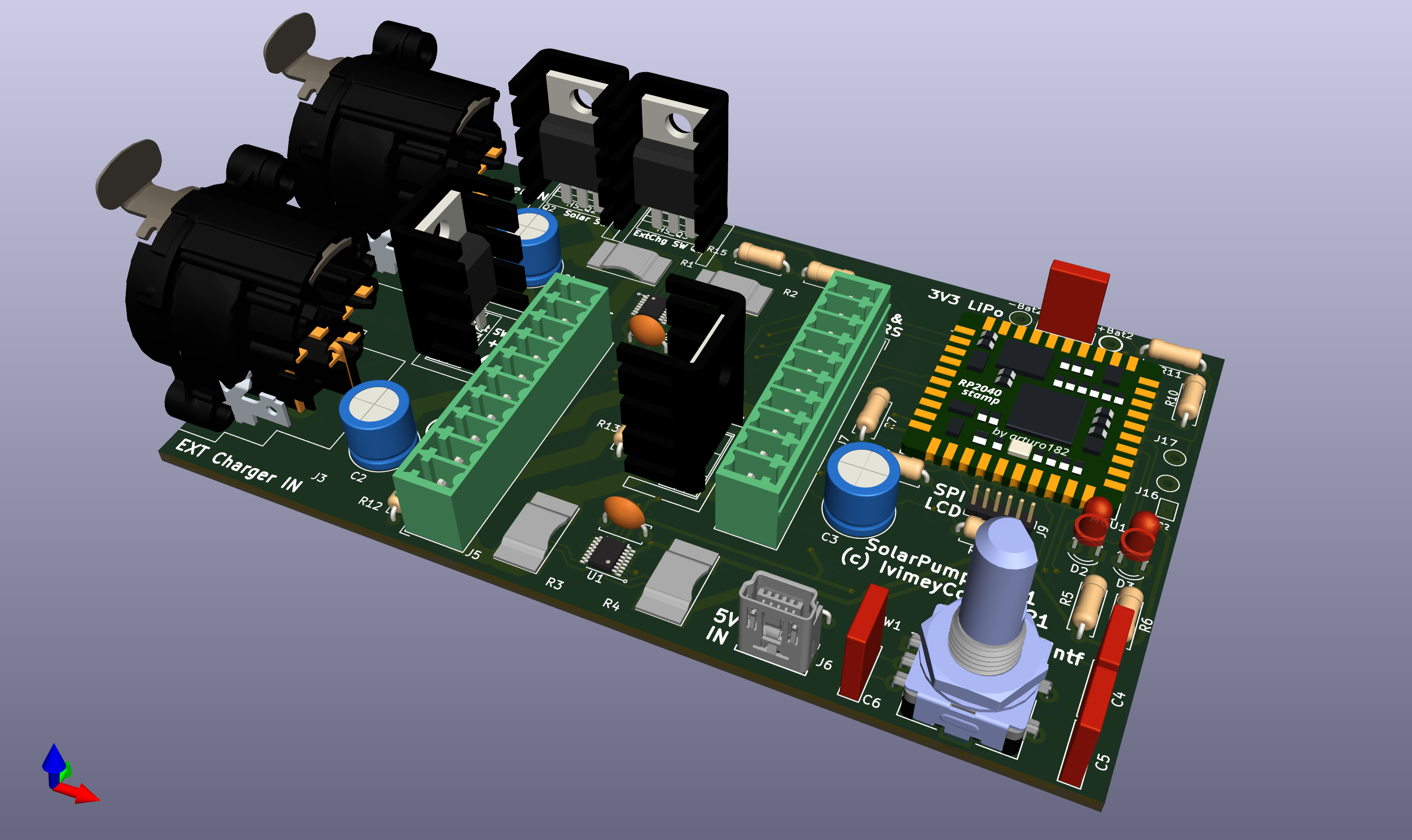
A second version was designed with the intention of supporting MPPT conversion and also to provide additional information about the current flows. This was because placement of the panel in the prevailing sunlight was easier when you have feedback on what is going on.
However, this second design was never built -- I was never sure enough it would work to make it worth getting a PCB built. I had done a lot of reading around the topic of MPPT converters and was starting to get some idea of the issues and constraints, and could see that what I had would probably have issues.
I did get as far as a KiCad PCB design, though:
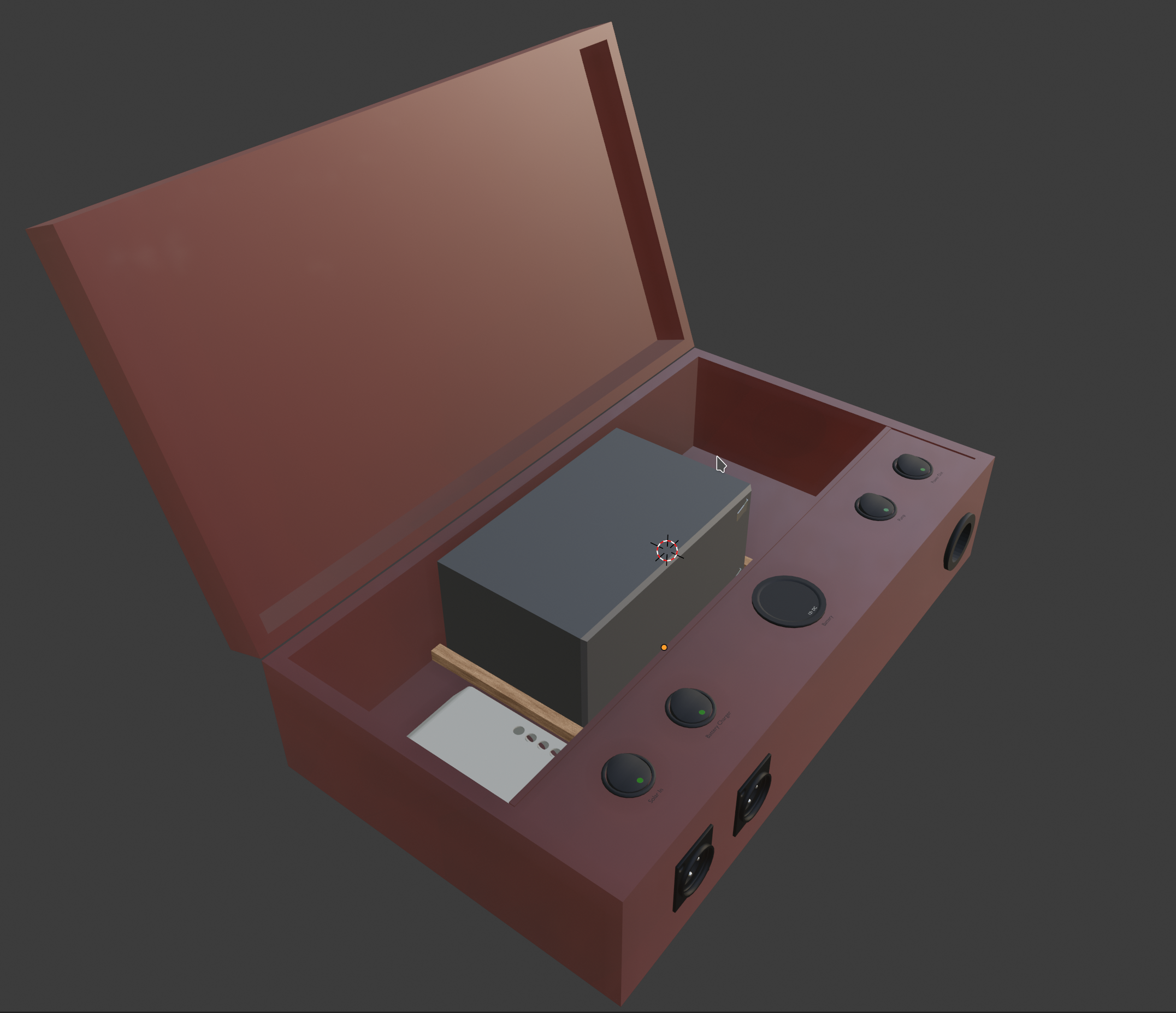
A new version was built... mostly using the components of the first version in a larger box (a two bottle "wine presentation" box with a nice looking, and water repellant, red varnish). This allowed a much better arrangement of the wiring, and made room for a 12V Car Accessory connector, which was supposed to be helpful for a camping trip.
For this version, a 3D CAD model was built in Blender 3D to verify the dimensions and fit.
An Intervention came along, in the way of the "DIY 1KW MPPT Solar Charge Converter" build, published on Instructables. This finally showed a path -- to be fair, not so very different from my earlier attempt but far better explained and, critically, tested! I resolved to rebuild my earlier design around this base.
The Instructables build is https://www.instructables.com/DIY-1kW-MPPT-Solar-Charge-Controller/ and there are links to the firmware and design files in that article.
A design goal for this version was to increase the flow rate somewhat, as although the existing pump worked, it was rather slow. I eventually settled on the Seaflo 41 Series DC Water System Pump 12V 12.5 LPM, which is up to about 2.5x higher flow rate.
Another design goal is to support measurement of water flow rate, so the unit can keep track of total water pumped and water pumped per session. While not strictly necessary this was something I felt was important.
Compared to that version, I decided to:
use the Solderparty RP2040 Stamp, partly because I had it and like it;
use an alternate half-bridge driver, because the 2104/5 is out of stock at present and the new one integrates a diode;
use an alternate current sensor (ACS758), because the article was quite critical of the one suggested (ACS712). I can't tell from the datasheet if it's an improvement, though :-(
use more current sensors, to avoid needing to estimate current output from current input, partly to monitor more things directly;
use 3 separate SM power supply devices for local power, rather than the arrangement in the original, which looked clunky;
use a different, and 8 channel, ADC to measure the extra circuits, and also enabling fast 16-bit sampling and faster MCU comms via SPI. It's slightly more expensive but not a lot, and overall better;
The big change I added was one I alluded to in an earlier mail: I essentially have 2 separate buck converters now, rather than just one, because I wanted to:
support MPPT input (eg. 18V);
support a controllable battery voltage for charging/float purposes (eg. 15V);
support a controllable output voltage (sep from battery) to e.g. control DC pump speed (eg. 9V to 12.5V).
So I've essentially got: MPPT => [Battery] => Simple Buck => Output.
This circuit then has two, switchable, outputs, rather than one, which I hope I've designed right this time! The purpose is to support a fixed link to the pump, plus an 'Aux' circuit for e.g. a car cig socket, for use when e.g. camping. My intention is that the two outputs are not used at the same time, but the circuit allows that option. I decided that USB power delivery, while nice, would be via a commercial car adapter, not built in.
I have derated the components slightly compared to the original, supporting only up to 48V input and up to about current output 18A rather than the 80V and 30A original, as this is meant to be a portable unit and not destined for huge batteries or panel arrays. On the battery front I'm intending to change from a 12V lead acid battery to a 4S3P Lithium one based on twelve 18650 batteries + controller for a 14V output. It should help reduce the weight (the new pump, now 3 gal/min rather than 1gal/min of earlier, is heavier!).
The second smaller board is for a 'front panel', which I envisage with a large "emergency stop" pushbutton, a digital rotary encoder, and a Pimoroni "Pico Display Hat", which is a small LCD on a 40pin R-Pi Pico footprint with 4 small pushbuttons and an RGB led. Most of that is interfaced via an MCP 16-pin IO adapter on the I2C bus, except for the SPI bus for the display itself.
Not shown in the circuit because it's off-board, the main on/off switch will be an SPST switch between the battery and the PCB.
Some pictures of the build so far (from KiCad):


| Qty | Value | Footprint | References |
|---|---|---|---|
| 37 | 0.1uF | Capacitor_SMD:C_0603_1608Metric | C1, C2, C3, C4, C19, C20, C22, C23, C24, C26, C27, C28, C30, C31, C49, C118 +21 |
| 29 | 0.1uF | Capacitor_SMD:C_0402_1005Metric | C6, C10, C12, C13, C33, C34, C35, C36, C37, C39, C40, C101, C102, C106, C107, C108 +13 |
| 25 | 10k | Resistor_SMD:R_0603_1608Metric | R17, R19, R23, R26, R29, R30, R33, R66, R100, R101, R106, R108, R109, R113, R114, R117 +9 |
| 13 | Red,150mcd | LED_SMD:LED_1206_3216Metric_Pad1.42x1.75mm_HandSolder | D1, D6, D7, D10, D17, D24, D25, D29, D30, D31, D32, D33, D34 |
| 12 | Mount | MountingHole:MountingHole_4.3mm_M4 | H1, H2, H3, H4, H5, H6, H7, H8, H9, H10, H11, H12 |
| 11 | TVS | Package_TO_SOT_SMD:SOT-23 | TVS1, TVS2, TVS3, TVS4, TVS5, TVS6, TVS7, TVS8, TVS9, TVS10, TVS11 |
| 9 | 10K | Resistor_SMD:R_0603_1608Metric | R7, R9, R11, R12, R31, R34, R84, R89, R119 |
| 9 | SQM120P10 | Package_TO_SOT_SMD:TO-263-2 | Q2, Q3, Q16, Q18, Q19, Q22, Q23, Q25, Q26 |
| 8 | 0.1uF,100V Tant | Capacitor_SMD:C_0805_2012Metric_Pad1.18x1.45mm_HandSolder | C17, C18, C111, C112, C113, C114, C115, C116 |
| 8 | 100R | Resistor_SMD:R_0603_1608Metric | R15, R16, R37, R38, R85, R86, R92, R93 |
| 6 | 12pF | Capacitor_SMD:C_0402_1005Metric | C15, C16, C42, C43, C104, C105 |
| 6 | 1uF | Capacitor_SMD:C_0603_1608Metric | C54, C66, C69, C78, C100, C103 |
| 6 | 27R | Resistor_SMD:R_0603_1608Metric | R13, R14, R35, R36, R90, R91 |
| 6 | BCR430UW6 | Package_TO_SOT_SMD:SC-74-6_1.55x2.9mm_P0.95mm | U32, U33, U34, U35, U36, U37 |
| 6 | IRLB8721PBF | Package_TO_SOT_THT:TO-220-3_Vertical | Q10, Q11, Q12, Q13, Q14, Q15 |
| 5 | 22K | Resistor_SMD:R_0603_1608Metric | R3, R57, R58, R59, R60 |
| 5 | 470k | Resistor_SMD:R_0603_1608Metric | R18, R22, R102, R110, R115 |
| 5 | 72R | Resistor_SMD:R_0603_1608Metric | R39, R40, R63, R94, R95 |
| 5 | B150-E3,50V | Diode_SMD:D_SMA | D4, D8, D11, D26, D27 |
| 5 | Fuse 25A | Fuse:Fuse_Schurter_UMZ250 | F1, F2, F3, F4, F5 |
| 5 | IPP019N08NF2S | Package_TO_SOT_THT:TO-220-3_Vertical | Q4, Q5, Q6, Q7, Q8 |
| 5 | JST SM03B-SRSS-TB | Connector_JST:JST_SH_SM03B-SRSS-TB_1x03-1MP_P1.00mm_Horizontal | J13, J20, J21, J26, J27 |
| 5 | SMAJ54CA | Diode_SMD:D_SMA | D2, D19, D22, D23, D28 |
| 4 | 0R | Resistor_SMD:R_0603_1608Metric | R27, R28, R76, R77 |
| 4 | 1K | Resistor_SMD:R_0603_1608Metric | R53, R54, R55, R56 |
| 4 | 1uF | Capacitor_SMD:C_0402_1005Metric | C11, C14, C38, C41 |
| 4 | 3K3 | Resistor_SMD:R_0603_1608Metric | R1, R4, R5, R118 |
| 4 | 4.7k,0.5% | Resistor_SMD:R_0603_1608Metric | R24, R25, R80, R81 |
| 4 | BC817 | Package_TO_SOT_SMD:SOT-23 | Q1, Q17, Q21, Q24 |
| 4 | HSink | MountingHole:MountingHole_2.7mm_M2.5_Pad_Via | HS1, HS2, HS3, HS4 |
| 3 | 10K NTC | solarpump:SolderWire-0.15sqmm_1x02_P3.5mm_D0.5mm_OD1.5mm | TH1, TH2, TH3 |
| 3 | 10uF | Capacitor_SMD:C_0603_1608Metric | C61, C117, C120 |
| 3 | 22uF,>35V | Capacitor_Tantalum_SMD:CP_EIA-7360-38_Kemet-E | C84, C85, C86 |
| 3 | 33k | Resistor_SMD:R_0603_1608Metric | R103, R111, R116 |
| 3 | 4.7k | Resistor_SMD:R_0603_1608Metric | R43, R64, R65 |
| 3 | 42K | Resistor_SMD:R_0603_1608Metric | R99, R107, R112 |
| 3 | ACS71240LLCBTR-025B3 | Package_SO:SOIC-8_3.9x4.9mm_P1.27mm | U22, U26, U31 |
| 3 | Amass_XT30PW | solarpump:Amass_XT30PW | J17, J33, J34 |
| 3 | RP2040 | Package_DFN_QFN:QFN-56-1EP_7x7mm_P0.4mm_EP3.2x3.2mm_ThermalVias | U7, U14, U30 |
| 3 | SAMTEC_ET60_24S_2Pr_Pins | solarpump:SAMTEC_ET60T-000-3-08-D02-X-R1-S | J1, J7, J8 |
| 3 | SAMTEC_ET60_24S_2Pr_Socket | solarpump:SAMTEC_ET60S-000-3-08-D02-L-R1-S | J2, J3, J10 |
| 3 | SW_RESET | Button_Switch_SMD:SW_SPST_B3U-1000P | SW1, SW2, SW9 |
| 3 | USB_B_Micro | Connector_USB:USB_Micro-B_Amphenol_10104110_Horizontal | J15, J22, J28 |
| 3 | W25Q32JV | Package_SON:WSON-8-1EP_6x5mm_P1.27mm_EP3.4x4mm | U4, U13, U28 |
| 3 | XYDBPCNANF-12MHZ | Crystal:Crystal_SMD_2520-4Pin_2.5x2.0mm | Y1, Y2, Y3 |
| 2 | 0.1uF,100V | Capacitor_SMD:C_0805_2012Metric_Pad1.18x1.45mm_HandSolder | C109, C110 |
| 2 | 10AWG | PCM_Jumper_AKL:Jumper_P5.08mm_D1.2mm | JP1, JP2 |
| 2 | 10K | Potentiometer_SMD:Potentiometer_Bourns_TC33X_Vertical | RV1, RV2 |
| 2 | 10nF | Capacitor_SMD:C_0603_1608Metric | C21, C32 |
| 2 | 10uF,50V | Capacitor_SMD:C_0805_2012Metric_Pad1.18x1.45mm_HandSolder | C45, C47 |
| 2 | 1K,1% | Resistor_SMD:R_0603_1608Metric | R74, R83 |
| 2 | 1R,1W | PCM_Resistor_SMD_AKL:R_2512_6332Metric | R20, R21 |
| 2 | 1k | Resistor_SMD:R_0603_1608Metric | R72, R97 |
| 2 | 1uF,50V | Capacitor_SMD:C_0805_2012Metric_Pad1.18x1.45mm_HandSolder | C44, C46 |
| 2 | 33K,1% | Resistor_SMD:R_0603_1608Metric | R73, R82 |
| 2 | 4K7 | Resistor_SMD:R_0603_1608Metric | R6, R8 |
| 2 | 680R | Resistor_SMD:R_0603_1608Metric | R50, R51 |
| 2 | 680uF,63V | Capacitor_THT:CP_Radial_D16.0mm_P7.50mm | CP1, CP2 |
| 2 | 74LVC1G125 | Package_TO_SOT_SMD:SOT-23-5 | U5, U38 |
| 2 | ACS71240 | Package_SO:SOIC-8_3.9x4.9mm_P1.27mm | U8, U15 |
| 2 | ADS131M04-PW | Package_SO:TSSOP-20_4.4x6.5mm_P0.65mm | U10, U25 |
| 2 | Conn_DISP | Connector_PinHeader_2.00mm:PinHeader_2x08_P2.00mm_Vertical | J6, J9 |
| 2 | HCPL-314Js | Package_SO:SOIC-16W-12_7.5x10.3mm_P1.27mm | OC1, OC2 |
| 2 | L6398D | Package_SO:SOIC-8_3.9x4.9mm_P1.27mm | U11, U23 |
| 2 | LED_CHR | LED_SMD:LED_0603_1608Metric | D12, D13 |
| 2 | Orange,160mcd | LED_SMD:LED_1206_3216Metric_Pad1.42x1.75mm_HandSolder | D14, D15 |
| 2 | S07G-M | Diode_SMD:D_SMF | D20, D21 |
| 2 | SN65HVD234 | Package_SO:SOIC-8_3.9x4.9mm_P1.27mm | U12, U27 |
| 2 | Si2306BDS | Package_TO_SOT_SMD:SOT-23 | Q9, Q27 |
| 1 | 100K | Resistor_SMD:R_0603_1608Metric | R45 |
| 1 | 100uF | Capacitor_SMD:C_0603_1608Metric | C119 |
| 1 | 10K,0.5% | Resistor_SMD:R_0603_1608Metric | R47 |
| 1 | 10R | Resistor_SMD:R_0603_1608Metric | R120 |
| 1 | 10nF,100V | Capacitor_SMD:C_0805_2012Metric_Pad1.18x1.45mm_HandSolder | C25 |
| 1 | 150R | Resistor_SMD:R_0603_1608Metric | R71 |
| 1 | 1uF,16V Tant | Capacitor_SMD:C_0805_2012Metric_Pad1.18x1.45mm_HandSolder | C59 |
| 1 | 2.5k,0.5% | Resistor_SMD:R_0603_1608Metric | R42 |
| 1 | 21.8k,0.5% | Resistor_SMD:R_0603_1608Metric | R41 |
| 1 | 220R | Resistor_SMD:R_0603_1608Metric | R52 |
| 1 | 220k | Resistor_SMD:R_0603_1608Metric | R32 |
The 363 most common of 450 parts.
It measures 373.1 × 220.9 mm and has 4 copper layers, 1.76 mm thick.
450 parts, built around the RP2040, 74LVC1G125, SN65HVD234D and BCR430UW6. The full list of its parts is on this page, with links to each part's symbol and footprint where PCBKit's library has them.
From the rivimey/solarpump repository on GitHub, at the commit this page was made from: the board is solarpump.kicad_pcb and its schematic flow_fan.kicad_sch. PCBKit opens the board in the browser, with nothing to install.
Its repository states no licence, so its author keeps all rights: ask rivimey before reusing the design.
formulaslug/fs-3-schematics
Electrical Design Repository for fs-3 schematics and PCBs

variegated-coffee/open-lcc-board
Schematics and PCB files for the Open LCC hardware

i-Saac-IV/flexi-lamp
A touch-sensing lamp lamp made of flexible PCBs.


nhallsny/faraday-rescue
Open source battery for e-bikes made by the now-defunct Faraday Bicycles

OpenAVNS/OpenAVNS
Hardware, firmware, and mechanical design

botblox/RouterCoreCore-Baseboard-Designs
Open source design files for the breakout board (baseboard) for RouterCore.
