2 layers60.4 × 112.5 mm
 RickP/MC5000_DevKit6
An hardware puzzle that teaches the basics of programming.
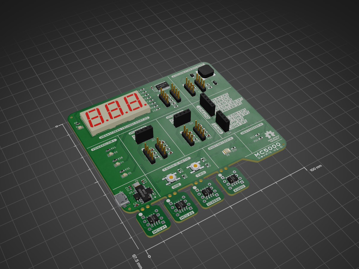
MC5000 Board is an open-source printed circuit board by RickP, from the RickP/MC5000_DevKit repository on GitHub, published under the GPL-3.0 licence. It is a 2-layer board of 100 × 97.5 mm with 131 parts on 105 nets, routed with 599 tracks and 108 vias.
It is built around the PFS173-S08, CH340G and SMD3528C-50, with the PCA9555PW, MLT-7525 and S9013 among its other parts. Its parts include 34 resistors, 21 connectors, 13 capacitors, 6 ICs and 6 diodes.


A development board that brings the Shenzhen IO game to real hardware.
This documentation is intended for people who want to build/extend/bugfix the hardware.
If you have an MC5000 DevKit board and want to play with it go to the user documentation.
I'm planning to order some ready-to-use boards if there are enough people interested. Drop me a message (pannen at gmail dot com) if you're interested in getting one or more
The project consists of three parts. The firmware for the PFS173 microcontroller used in this project, a circuit board that connects to a computer via USB and a cross-platform desktop application that is used to programm the board.
The main use of this is to teach beginners the basics of programming and electronics by solving problems with increasing difficulty. Users have to make electric connection on the circuit board with jumper cable and programm the two microcontrollers with a simplified assembler language to solve the tasks.

The board is designed in KiCAD 5, an OpenSource electronics CAD package. In the spirit of the game it is made with the cheapest components I could find.
The design files are contained in the subfolder 'pcb'. The production files that are needed to make completely assembled boards (Gerbers, Pick&Place, BOM) are compiled automatically and can be found on the releases page in the zip package "PCB_fabrication_files_for_jlcpcb.zip".
Currently everything optimized for the chinese board manufacturer JLCPB. Just upload the gerbers (2 layers, 1.6mm PCB), choose "SMT Assembly" and upload the BOM and Pick&Place file when asked for it. For some reason you can have green, black, red or blue boards if you order up to 30 boards. For 50 boards they have to be green or black. If you order 50 boards each one is under 7 Euros including shipping and taxes to the EU (with the 'EuroPackage' shipping option').
Please check if all components are mounted the right way around when ordering. I tried to make sure everything fits but I may not have ordered the latest iteration myself. Also it would be nice it you give me some feedback if you order these. E.g. mention me in a tweet about it (@r1ckp).
The board uses 4 Padauk PFS173 microcontrollers. These are super cheap chinese 8bit microcontrollers that cost about 8cent per piece. They have 3 kilowords of flash ROM and 256 bytes of RAM.
The firmware for the two application controllers (a.k.a. MC5000) and the buzzer and display controller are in the subfolder 'firmware'. They are made with the Free PDK toolchain an open-source toolchain for many of the Padauk microcontrollers. It uses the SDCC compiler suite.
The code structure may look a bit weird at first but I had to made some strange constructions to trick the compiler into using as little memory as possible as I was constantly running out of it. Make sure you use the version 4.1.0 of SDCC as it otimizes the code for the Padauk ICs much better than the 4.0.0 release.
In order to flash the ICs you have to make or buy an Easy PDK programmer. The programmer is open hardware. I got mine assempled from amazon but you can make one yourself production files. If you want to flash the firmware you need the programmer and the easy-pdk-programmer software.
With the SDCC compiler and easypdkprog in your path just place the breakout boards on the programmer and execute the makefiles:
cd firmware/MCU5000
make flash1       # Flash MCU1
make flash2       # Flash MCU2
cd ../BUZZER
make flash        # Flash Buzzer
cd ../DISPLAY
make flash        # Flash Display
Firmware binaries can be found on the releases page.
For binary flashing the two MCU5000 ICs have to be flashed with different CPU-IDs:
MCU1: easypdkprog -s 31 -n PFS173 write MC5000.PFS173.ihx
MCU2: easypdkprog -s 32 -n PFS173 write MC5000.PFS173.ihx
The two peripheral controllers are just flashed without a cpu id:
BUZZER: easypdkprog -n PFS173 write buzzer.PFS173.ihx
DISPLAY: easypdkprog -n PFS173 write display.PFS173.ihx
The desktop application parses the code to a binary format and uploads it to the virtual 'MC5000' controllers on the board. It's written in QT5 (Version 5.12.8) and compiled automatically into packages for Linux, MacOS and Windows. Installation instructions are part of the user documentation.
The code is very simplistic with a lot of room for improvents. It's contained within the 'gui' subdirectory. The binaries can be found on the releases page.
Currently there's a bug that prevents the rudimantary code error checking for MCU2!
The releases including binary packages for four platforms and PCB fabrication files are created by a github action (see ".github/workflows/main.yml"). It also signs the MacOS app with my certificate that is stored in github secrets. The built is triggered when the repository is tagged.
If you want the same functionality for the MacOS package on your own fork fork you have to add some secrets in "Project settings/Secrets/Repository secrets":
If you don't have an apple developer password you can also remove the signing part from the action. Be aware that this will make the installation of the app for MacOS users much less nice because they will get warnings and have to explicitly allow the execution in the security settings.
| Qty | Value | Footprint | References |
|---|---|---|---|
| 33 | buzzard_labels | , , , , , , , , , , , , , , , +17 | |
| 13 | 220R | Resistor_SMD:R_0603_1608Metric_Pad0.98x0.95mm_HandSolder | R1, R2, R3, R4, R5, R6, R7, R8, R21, R25, R28, R33, R35 |
| 11 | 0.1uF | Capacitor_SMD:C_0603_1608Metric_Pad1.08x0.95mm_HandSolder | C1, C2, C3, C4, C5, C6, C7, C8, C9, C10, C11 |
| 8 | Conn_01x04_Female | LCSC_parts:PinHeader_1x04_P2.54mm_Vertical_centered | J14, J15, J16, J18, J19, J21, J22, J23 |
| 8 | Conn_01x04_Male | LCSC_parts:PinHeader_1x04_P2.54mm_plug | J2, J3, J4, J5, J6, J7, J8, J9 |
| 7 | 2K2 | Resistor_SMD:R_0603_1608Metric_Pad0.98x0.95mm_HandSolder | R9, R10, R11, R15, R16, R19, R20 |
| 6 | 1M | Resistor_SMD:R_0603_1608Metric_Pad0.98x0.95mm_HandSolder | R12, R13, R14, R17, R18, R27 |
| 5 | 100K | Resistor_SMD:R_0603_1608Metric_Pad0.98x0.95mm_HandSolder | R12, R22, R23, R32, R34 |
| 4 | LED | LED_SMD:LED_0805_2012Metric_Pad1.15x1.40mm_HandSolder | D1, D3, D4, D5 |
| 4 | PFS173-S08 | LCSC_parts:SOP-8_3.9x4.9mm_P1.27mm_rotated | U1, U2, U3, U4 |
| 3 | Conn_01x04_Female | LCSC_parts:PinSocket_1x04_P2.54mm_Vertical_centered | J17, J20, J24 |
| 2 | 33pF | Capacitor_SMD:C_0603_1608Metric_Pad1.08x0.95mm_HandSolder | C12, C13 |
| 2 | SW_MEC_5E | Button_Switch_SMD:SW_Push_1P1T_NO_CK_KSC6xxJ | SW1, SW2 |
| 1 | 10K | Resistor_SMD:R_0603_1608Metric_Pad0.98x0.95mm_HandSolder | R26 |
| 1 | 120R | Resistor_SMD:R_0603_1608Metric_Pad0.98x0.95mm_HandSolder | R31 |
| 1 | CH340G | LCSC_parts:SOP-16_3.9x9.9mm_P1.27mm_rotated | U5 |
| 1 | Conn_01x05_Female | LCSC_parts:PinSocket_1x05_P2.54mm_Vertical_centered | J25 |
| 1 | Crystal_GND24 | Crystal:Crystal_SMD_3225-4Pin_3.2x2.5mm | Y1 |
| 1 | D | Diode_SMD:D_SOD-123F | D2 |
| 1 | MLT-7525 | LCSC_parts:MagneticBuzzer_7.5x7.5_SMT | BZ1 |
| 1 | NTC - 100k | Resistor_SMD:R_0603_1608Metric_Pad0.98x0.95mm_HandSolder | R24 |
| 1 | PCA9555PW | LCSC_parts:TSSOP-24_4.4x7.8mm_P0.65mm_rotated | U8 |
| 1 | S9013 | LCSC_parts:SOT-23_rotated | Q1 |
| 1 | SLR0523DYA1BD | LCSC_parts:SLR0523DYA1BD | DS1 |
| 1 | SMD3528C-50 | LCSC_parts:LED_1210_3225Metric_Pad1.42x2.65mm_rotated | D6 |
| 1 | USB_B_Micro | LCSC_parts:MicroXNJ | J1 |
The 119 most common of 131 parts.
It measures 100 × 97.5 mm and has 2 copper layers, 1.6 mm thick.
131 parts, built around the PFS173-S08, CH340G, SMD3528C-50 and PCA9555PW. The full list of its parts is on this page, with links to each part's symbol and footprint where PCBKit's library has them.
From the RickP/MC5000_DevKit repository on GitHub, at the commit this page was made from: the board is pcb/MC5000_Board.kicad_pcb. PCBKit opens the board in the browser, with nothing to install.
Its repository publishes it under the GPL-3.0 licence: you may reuse it on that licence's terms (keep the author's notice, and for a copyleft licence share your changes alike).


BornaBiro/Xmas-Ornament-2024
Issues is that STM32 MCU is missing it's GND.

alphaseneca/chronopixel-pcb
Hardware design and KiCad PCB files for the ChronoPixel smart matrix desk clock.


npgo22/APRL-Electrical-New
To use the board templates, set KICADUSERTEMPLATEDIR by: