2 layers
Nrf bga
github-linguist/linguist
Language Savant. If your repository's language is being reported incorrectly, send us a pull request!
12 parts14kMIT

 richClubb/led-clock2
A desk or wall based LED clock
Led clock prototype is an open-source printed circuit board by richClubb, from the richClubb/led-clock repository on GitHub. It is a 2-layer board with 12 parts on 20 nets.
Its parts include 5 resistors, 3 switches, 2 ICs and 2 connectors. It belongs with the lEDs and displays boards of this library.
A desk or wall LED clock based on the LED rings
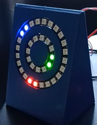
The idea is that this is could be a product that I could sell, either as a finished clock or as a kit, but it's easy enough that it can be assembled by secondary school students.
This video shows the movements of seconds, minutes and hours and how they blend together and move around the rings.
This video shows the colour change config of the seconds unit. It can also be re-assigned to either of the two rings
This video shows the timer working. The timer is for 10s and then flashes to show completion.
| Qty | Value | Footprint | References |
|---|---|---|---|
| 5 | R_Small | Resistor_SMD:R_1206_3216Metric_Pad1.30x1.75mm_HandSolder | R1, R2, R3, R4, R5 |
| 2 | Conn_01x03 | Connector_PinHeader_2.54mm:PinHeader_1x03_P2.54mm_Vertical | J1, J2 |
| 1 | SW_DOWN | Button_Switch_THT:SW_PUSH_6mm | SW3 |
| 1 | SW_MODE | Button_Switch_THT:SW_PUSH_6mm | SW1 |
| 1 | SW_UP | Button_Switch_THT:SW_PUSH_6mm | SW2 |
| 1 | ~ | Connector_PinHeader_2.54mm:PinHeader_1x06_P2.54mm_Vertical | U2 |
| 1 | ~ | Waveshare:Waveshare_ESP32_C3_Zero | U1 |
12 parts. The full list of its parts is on this page, with links to each part's symbol and footprint where PCBKit's library has them.
From the richClubb/led-clock repository on GitHub, at the commit this page was made from: the board is hardware/led-clock-prototype/led-clock-prototype.kicad_pcb and its schematic hardware/led-clock-prototype/led-clock-prototype.kicad_sch. PCBKit opens the board in the browser, with nothing to install.
Its repository states no licence, so its author keeps all rights: ask richClubb before reusing the design.
github-linguist/linguist
Language Savant. If your repository's language is being reported incorrectly, send us a pull request!


google/mozc-devices
Circuit diagrams and firmware source code for Gboard DIY keyboards


hackclub/OnBoard
💡 Join 1,000 teenagers and make your first PCB with a $100 grant!

VoronDesign/Voron-Tap
Tap is a nozzle-based z-probe for the V2 and Trident printer designs. The entire toolhead moves to trigger an optical switch. Tap offers many advantages:

stacksmashing/pico-tpmsniffer
A simple, very experimental TPM sniffer for LPC bus