
4 layers16.9 × 119.4 mm
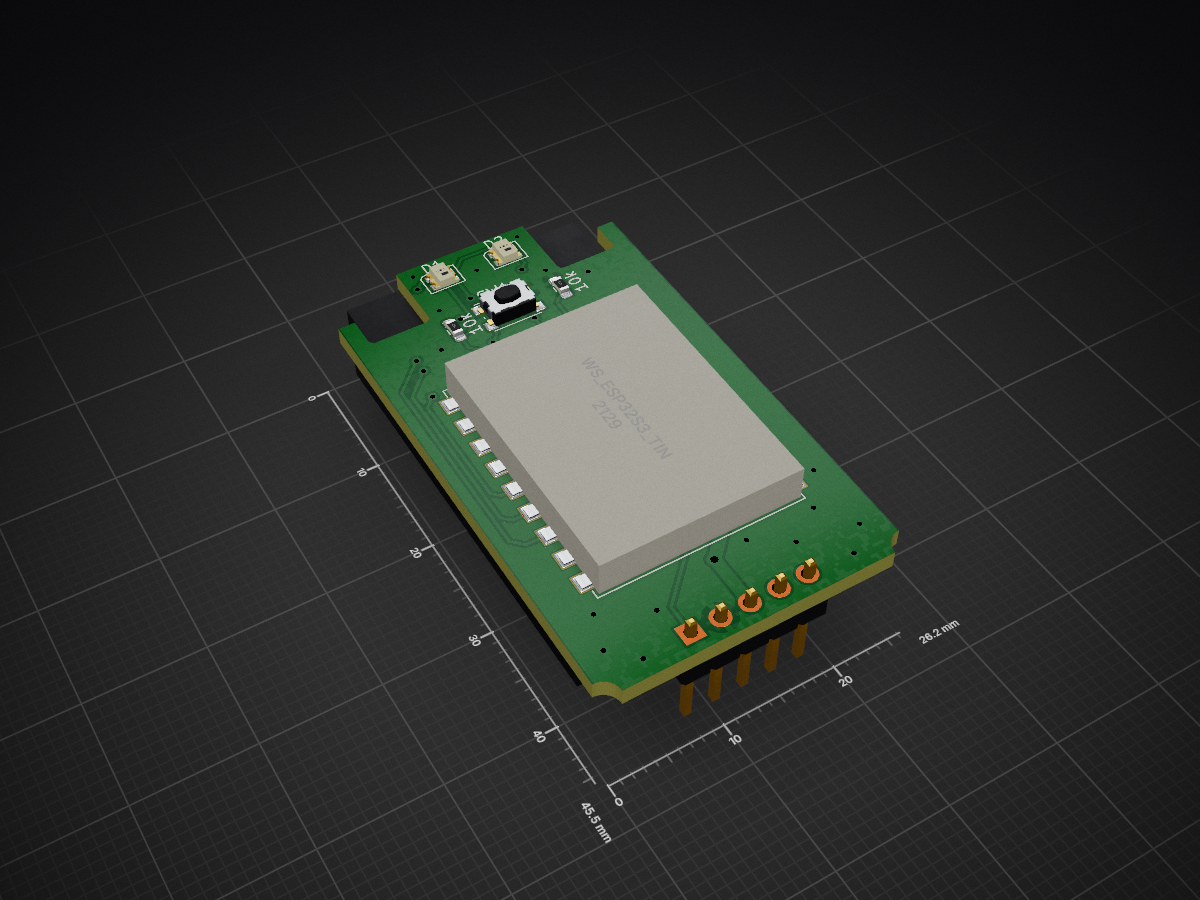
 richardclli/PL18-ELRS-Module1
A DIY internal ExpressLRS transmitter module for the Flysky Paladin PL18 radio, repurposing the stock FRM301 module's casing and RF module.
PL18 ELRS is an open-source printed circuit board by richardclli, from the richardclli/PL18-ELRS-Module repository on GitHub, published under the MIT licence. It is a 2-layer board of 26.2 × 45.5 mm with 8 parts on 29 nets, routed with 121 tracks and 69 vias.
It is built around the WS2812B-2020. Its parts include 2 resistors, 2 ICs, 2 diodes, 1 connector and 1 switch. It belongs with the ESP32 boards of this library.
A DIY internal ExpressLRS transmitter module for the Flysky Paladin PL18 radio, repurposing the stock FRM301 module's casing and RF module.
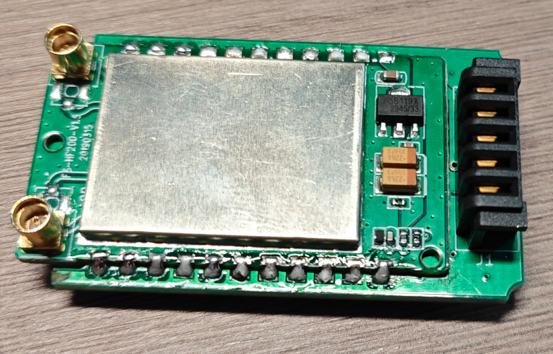
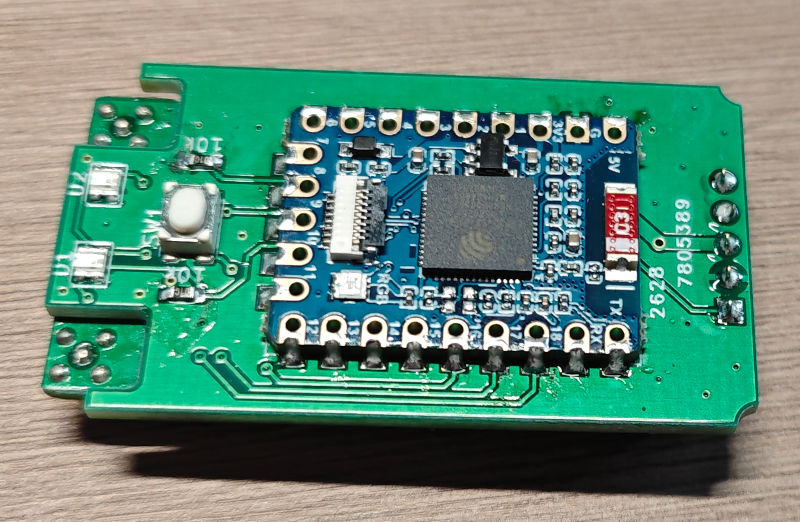
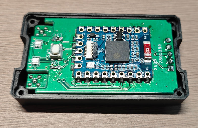
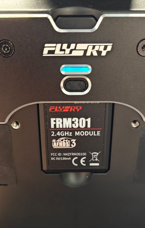
The Flysky PL18 ships with the FRM301 external TX module. This project replaces the FRM301's internal PCB with a custom carrier board that combines a Waveshare ESP32-S3-Tiny as the protocol bridge and the FRM301's HF200 RF module as the 2.4GHz ExpressLRS frontend. The result is a fully-featured, drop-in ExpressLRS transmitter module that fits the existing module bay and communicates with the radio over its 5-pin SPORT port.
| Ref | Part | Qty | Notes |
|---|---|---|---|
| — | PL18-ELRS PCB | 1 | Order using the Gerber files in this repo |
| — | FRM301 donor module | 1 | Harvest the HF200 RF module and the plastic casing |
| U1 | Waveshare ESP32-S3-Tiny | 1 | Product page |
| U2 | HF200 RF module | 1 | Desoldered from the FRM301 |
| D1, D2 | WS2812B-2020 | 2 | 2.0×2.0mm PLCC4 package RGB LED |
| R1, R2 | 10kΩ 0603 resistor | 2 | |
| SW1 | KMR2 tactile switch | 1 | 3.2×4.2mm |
| J1 | 5-pin 2.54mm male header | 1 | DS-B01F-A-S2 or equivalent |
| Pin | Signal | ESP32-S3 GPIO | Description |
|---|---|---|---|
| 1 | SPORT | IO04 | S.Port (bidirectional CRSF protocol) |
| 2 | GND | — | Ground |
| 3 | +5V | — | 5V power input from radio |
| 4 | NC | — | Not connected |
| 5 | NC | — | Not connected |
| ESP32-S3 GPIO | HF200 Pin | Function |
|---|---|---|
| IO04 | — | SPORT (to PL18 connector) |
| IO06 | TXEN | TX enable |
| IO07 | RXEN | RX enable |
| IO08 | DI01 | Bidirectional data |
| IO09 | BUSY | Busy status (input) |
| IO10 | SPI_NSS | SPI chip select |
| IO11 | SPI_MOSI | SPI MOSI |
| IO12 | SPI_CLK | SPI clock |
| IO13 | SPI_MISO | SPI MISO |
| IO14 | RESET | HF200 reset |
| IO15 | L_ANT_SW | Left antenna switch |
| IO16 | R_ANT_SW | Right antenna switch |
| IO17 | SW1 | Boot button (active low) |
| IO18 | D1 DIN | WS2812B LED data line |
| Rail | Source | Supplies |
|---|---|---|
| +5V | PL18 connector (J1) | ESP32-S3-Tiny (U1), HF200 (U2) |
| +3V3 | ESP32-S3 internal regulator | WS2812B LEDs (D1, D2), L_POWER pull-up (R2) |
The PCB design was created in KiCad 10.0.
| File | Description |
|---|---|
PL18_ELRS.kicad_pro | KiCad project file |
PL18_ELRS.kicad_sch | Schematic |
PL18_ELRS.kicad_pcb | PCB layout |
Multi.kicad_sym | Custom symbol library |
Multi.pretty/ | Custom footprint library |
The custom footprints include the WS_ESP32S3_Tiny (23-pin SMT module) and HF200-SMT (22-pin RF module) footprints matched to the donor parts.
The ExpressLRS target definition for the Flysky PL18 is maintained at:
github.com/richardclli/ELRS-targets
After flashing, configure ExpressLRS to use the SPORT protocol for telemetry.
The repository includes a complete set of manufacturing outputs in the root directory:
| File | Description |
|---|---|
PL18_ELRS-F_Cu.gbr | Top copper |
PL18_ELRS-B_Cu.gbr | Bottom copper |
PL18_ELRS-F_Mask.gbr | Top solder mask |
PL18_ELRS-B_Mask.gbr | Bottom solder mask |
PL18_ELRS-F_Paste.gbr | Top solder paste |
PL18_ELRS-B_Paste.gbr | Bottom solder paste |
PL18_ELRS-F_Silkscreen.gbr | Top silkscreen |
PL18_ELRS-B_Silkscreen.gbr | Bottom silkscreen |
PL18_ELRS-Edge_Cuts.gbr | Board outline |
PL18_ELRS-PTH.drl | Plated through-hole drill |
PL18_ELRS-NPTH.drl | Non-plated through-hole drill |
To order PCBs, zip all Gerber and drill files and upload to your preferred fab (JLCPCB, PCBWay, etc.) with these specs:
This project is licensed under the MIT License — see the LICENSE file for details.
| Qty | Value | Footprint | References |
|---|---|---|---|
| 2 | 10k | Resistor_SMD:R_0603_1608Metric_Pad0.98x0.95mm_HandSolder | R1, R2 |
| 2 | WS2812B-2020 | LED_SMD:LED_WS2812B-2020_PLCC4_2.0x2.0mm | D1, D2 |
| 1 | HF200 | Multi:HF200-SMT | U2 |
| 1 | PL18 | Multi:DS-B01F-A-S2 | J1 |
| 1 | SW_Push | Multi:SW_Push_3.2x4.2 | SW1 |
| 1 | WS_ESP32S3_Tiny | Multi:WS_ESP32S3_Tiny | U1 |


VimDrones/AM32_esc_development_board
Open Source AM32 ESC development board

rianadon/Cosmos-Keyboard-PCBs
Open-Source keyboard PCB designs for the Cosmos Keyboard Generator

phil31/NerdEKO-Gamma
fork of the NerdOCTAXE-Gamma design (https://github.com/Patsch91/NerdOCTAXE-Gamma), with 12 x BM1370 (14TH/s SHA256)
It measures 26.2 × 45.5 mm and has 2 copper layers, 1.6 mm thick.
8 parts, built around the WS2812B-2020. The full list of its parts is on this page, with links to each part's symbol and footprint where PCBKit's library has them.
From the richardclli/PL18-ELRS-Module repository on GitHub, at the commit this page was made from: the board is PL18_ELRS.kicad_pcb and its schematic PL18_ELRS.kicad_sch. PCBKit opens the board in the browser, with nothing to install.
Its repository publishes it under the MIT licence: you may reuse it on that licence's terms (keep the author's notice, and for a copyleft licence share your changes alike).