
2 layers99.1 × 99.1 mm
I2CHWC
riban-bw/I2C-Hardware-Controller
A hardware controller providing rotary encoders, switches and potentiometer values via I2C
79 parts4GPL-3.0
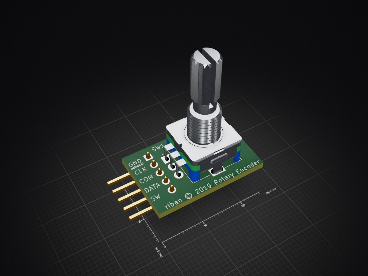
A hardware controller providing rotary encoders, switches and potentiometer values via I2C
Encoder is an open-source printed circuit board by riban-bw, from the riban-bw/I2C-Hardware-Controller repository on GitHub, published under the GPL-3.0 licence. It is a 2-layer board of 25.4 × 16.5 mm with 2 parts on 5 nets, routed with 12 tracks and 0 vias.
Its parts include 1 connector and 1 switch.
A hardware controller providing rotary encoders, switches and potentiometers, interfacing with a host / master device via I2C 2-wire serial link and interrupt pin.
I2C Hardware Controller provides an interface to other applications via 30 continuous rotary encoders, 50 on / off switches and 64 end-stopped variable resistors (potentiometers). The link to the host device is via I2C which requires a clock and data signal. Power may be provided by the host as 3.3V or 5V. (Both devices must have a common ground.) The host may continuously poll the hardware controller (HWC) for changes or use a dedicated GPI signal to trigger interrupts (or similar event handling routine). Several HWC may be cascaded to increase the quantity of controls as required sharing I2C bus but each with its own individual interrupt GPI.
Rotary encoders provide the value of change since last read which is a positive integer for clockwise rotation and negative for counter-clockwise rotation. Slow rotation changes value by one unit whilst faster rotation changes value by ten units. It is the responsibility of the host device / application to store the absolute value calculated from the relative position values sent by the HWC.
Switches provide on / off value with contact bounce filtering to avoid false re-triggering. Rotary encoders commonly include a push switch which may be wired as a switch control or separate push buttons / toggle switches / slide switches / etc. may be attached.
Note: Switches and rotary encoders are X-Y multiplexed so cannot use a common ground, i.e. both polls of each switch and all three pins of a rotary encoder need to be connected to the HWC matrix. To simplify wiring, each rotary encoder and associated swich share a common matrix pin resulting in each rotary encoder / switch combination requiring 4 wires.
End-stopped variable resistance (potentiometer) controls provide a maximum of 12-bit resolution. A noise filter is applied which increases the latency and / or reduces the resolution of ADC. (Each bit reduction improves latency by one sample period and reduces noise.) Noise is the re-triggering of analogue values when there is no physical change of knob position. At 12-bit resolution this is quite common but reducing to 10-bits (default) cleans the signal significantly. The required filter may depend on the quality of potentiometer and wiring.
Note: End-stopped controls are multiplexed but share common +3.3V and 0V supply rails which may ease wiring but care should be taken to avoid electrical noise.
The core of the HWC is a STM32F103 from STMicroelectronics in the form of a Maple Leaf Mini development board. (Blue Pill board may be used with some modification to code - this may be accomodated in a future code update. Blue Pill shares common digital and analogue supplies so may be liable to more noise interference.) This board accepts 5V or 3.3V supply. It operates at 3.3V with some 5V tolerant pins. The HWC is designed to interface with 3.3V devices, e.g. Raspberry Pi but may work with 5V devices without modification.
8 potentiometers may be connected directly to the ADC inputs or up to 64 potentiometers may be connected via 8 x CD4051B analogue multiplex chips. To use the multiplexers, configuration bit 6 must be set with a jumper. Unused inputs are tied to ground to avoid false trigger due to noise. Separation of analogue and digital supply and ground is recommend as provided by the Maple Leaf Mini (but not the Blue Pill board). Suitable noise filtering capacitors should be placed between the analogue supply rails periodically.
The switches and rotary encoders (which are just a pair of bi-phase oriented switches) are connected as a X-Y matrix with a 1N4148 signal diode between one switch pole and the matrix bus. Fewer switches or rotary encoders may be connected as required.
The HWC acts as a I2C slave with I2C address configurable at boot time (via 6 DIP switches giving address range 0x08 - 0x47). The default with no links is 0x08. Connections to the master device is via 3 signal wires and 2 power wires thus:
    ---------------------                      -----------------------
    |                   |-------3.3/5V-------->|                     |
    | Master I2C device |-------I2C CLK------->| Hardware Controller |
    | e.g. Raspberry Pi |<------I2C SDA------->|                     |
    |                   |<--------INT----------|                     |
    |                   |---------0V-----------|                     |
    ---------------------                      -----------------------
The INT pin is held high under normal condition and goes low (0V) when there has been a change of value of any controller on the HWC. When all changed values have been read by the I2C master the INT signal returns high.
The I2C master may request the value of any control by sending the control number (1...144) as a single byte message then reading a 16-bit (two byte) response. If the I2C master sends a request for controller zero, the next I2C read will return the index of the first controller with a value that has changed since its last read. Pseudo code may look like:
while(GPI_INT == 0) {
  reg = I2C_GET_REG(0);
  if(reg != 0) {
    value = I2C_GET_REG(reg);
  }
}
Data value for potentiometers is a positive integer range 0..(2^n - 1) where n=number of bits, e.g. 0..4095 for 12-bit ADC. Data value for switches is 0 for off (open) and 1 for on (closed). Data value for rotary encoders is -1 for single counter-clockwise rotation detent and +1 for single clockwise rotation detent. If rotated faster than queried by I2C master then the relative offset increases accordingly, e.g. if rotated clockwise by 4 detents since last query, the next query result will be +4. This value must be read as a 16-bit signed integer.
The HWC has 144 registers, one for each possible control. Unpopulated controls will return a zero value.
| Register | Use | Range |
|---|---|---|
| 0 | Index of next control that has changed | 0 - 144 (0 for no change) |
| 1 - 64 | Potentiometers 1 - 64 | 0 - 4096 |
| 65 - 114 | Switches 1 - 50 | 0 - 1 |
| 115 - 144 | Encoders 1 - 30 | -32768 - 32767 |
It is possible to write a command to register 0.
| Command ID | Command | Parameters |
|---|---|---|
| 0 | Reset | Resets all values to zero and clears dirty flags (and hence interrupt) |
| Qty | Value | Footprint | References |
|---|---|---|---|
| 1 | Conn_01x05_Male | Connector_PinHeader_2.54mm:PinHeader_1x05_P2.54mm_Horizontal | J1 |
| 1 | Rotary_Encoder_Switch | Rotary_Encoder:RotaryEncoder_Alps_EC11E-Switch_Vertical_H20mm | SW1 |
riban-bw/I2C-Hardware-Controller
A hardware controller providing rotary encoders, switches and potentiometer values via I2C

riban-bw/I2C-Hardware-Controller
A hardware controller providing rotary encoders, switches and potentiometer values via I2C

riban-bw/I2C-Hardware-Controller
A hardware controller providing rotary encoders, switches and potentiometer values via I2C

hzeller/rpi-rgb-led-matrix
Controlling up to three chains of 64x64, 32x32, 16x32 or similar RGB LED displays using Raspberry Pi GPIO


adamws/kicad-kbplacer
KiCad plugin for automatic keyboard's key placement and routing

Luos-io/luos_engine
Open-source and real-time orchestrator for cyber-physical-systems, to easily design, test and deploy embedded applications and digital twins.

NVNTLabs/switch2-SDEX2M2
Micro SD Express to M.2 NVME Adapter for Nintendo Switch 2

BlueSCSI/BlueSCSI-v2
BlueSCSI v2/Ultra - an open source, open hardware, SCSI emulator using the Pi Pico PR2040 and Pico 2 RP2350

ohmtech-rdi/eurorack-blocks
Software to Hardware Prototyping for Eurorack using C++, Max/Gen~ or Faust

It measures 25.4 × 16.5 mm and has 2 copper layers, 1.6 mm thick.
2 parts. The full list of its parts is on this page, with links to each part's symbol and footprint where PCBKit's library has them.
From the riban-bw/I2C-Hardware-Controller repository on GitHub, at the commit this page was made from: the board is hardware/Encoder/Encoder/Encoder.kicad_pcb. PCBKit opens the board in the browser, with nothing to install.
Its repository publishes it under the GPL-3.0 licence: you may reuse it on that licence's terms (keep the author's notice, and for a copyleft licence share your changes alike).