2 layers320 × 150 mm
 RetroStack/BitStack-DigiMind
A simple game to learn digital electronics
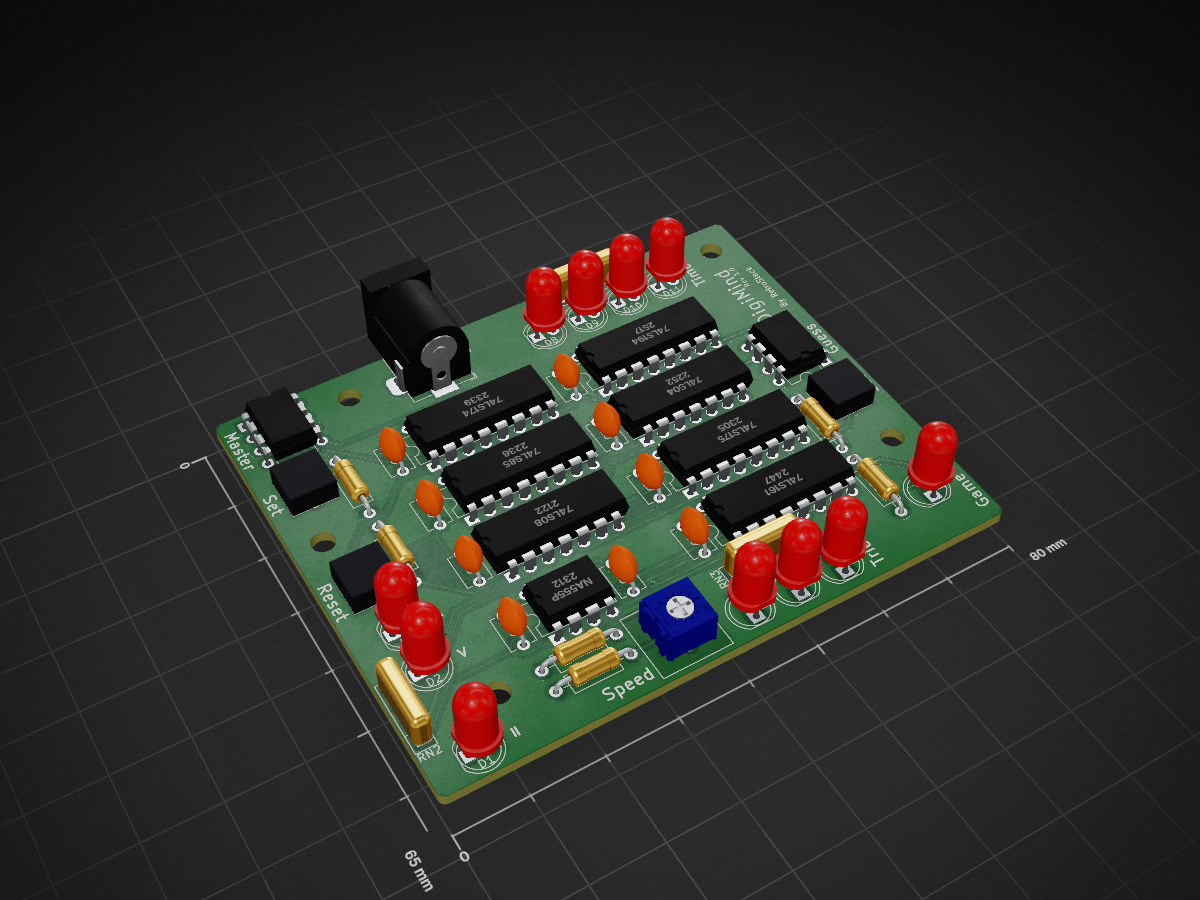
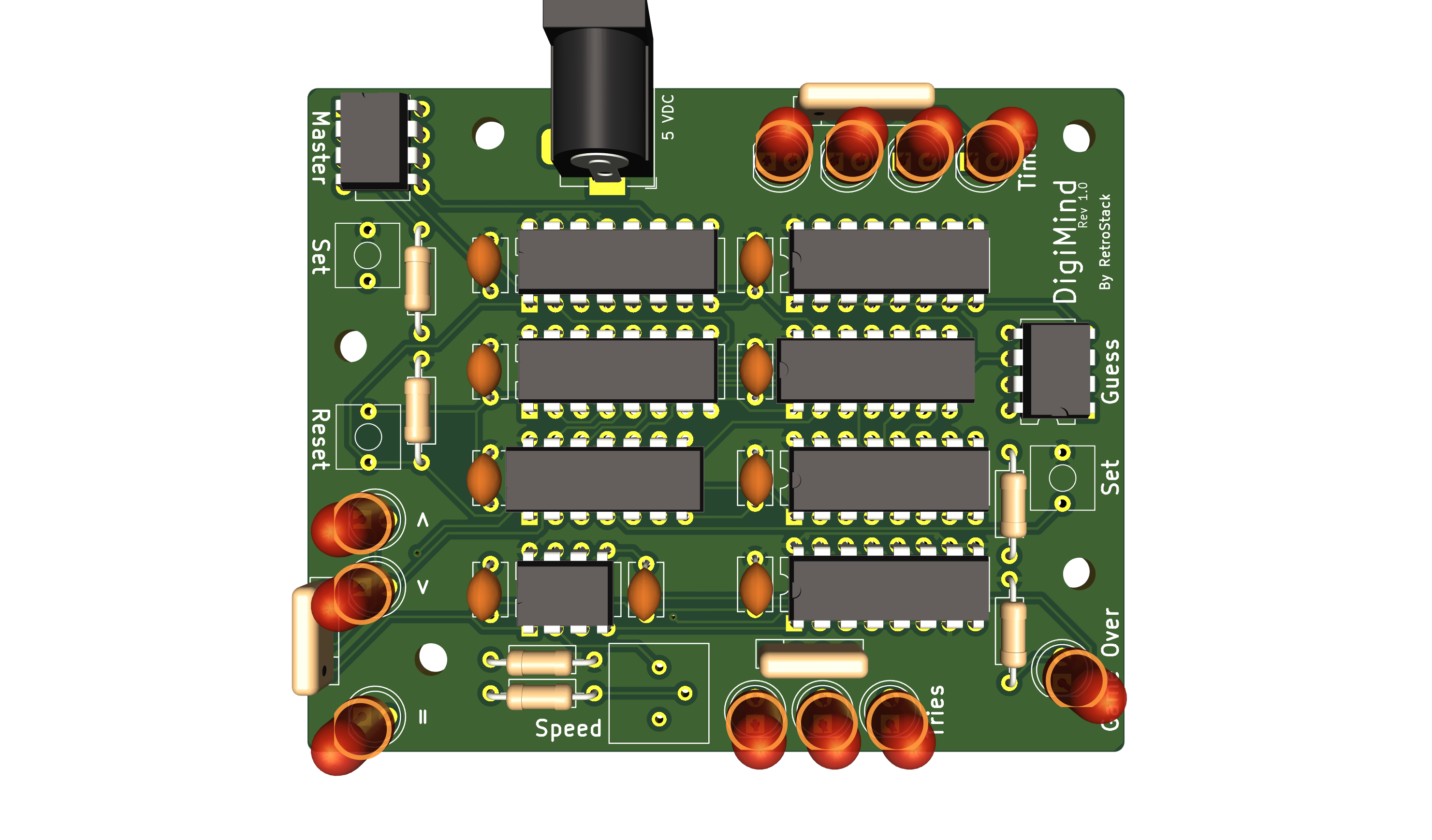
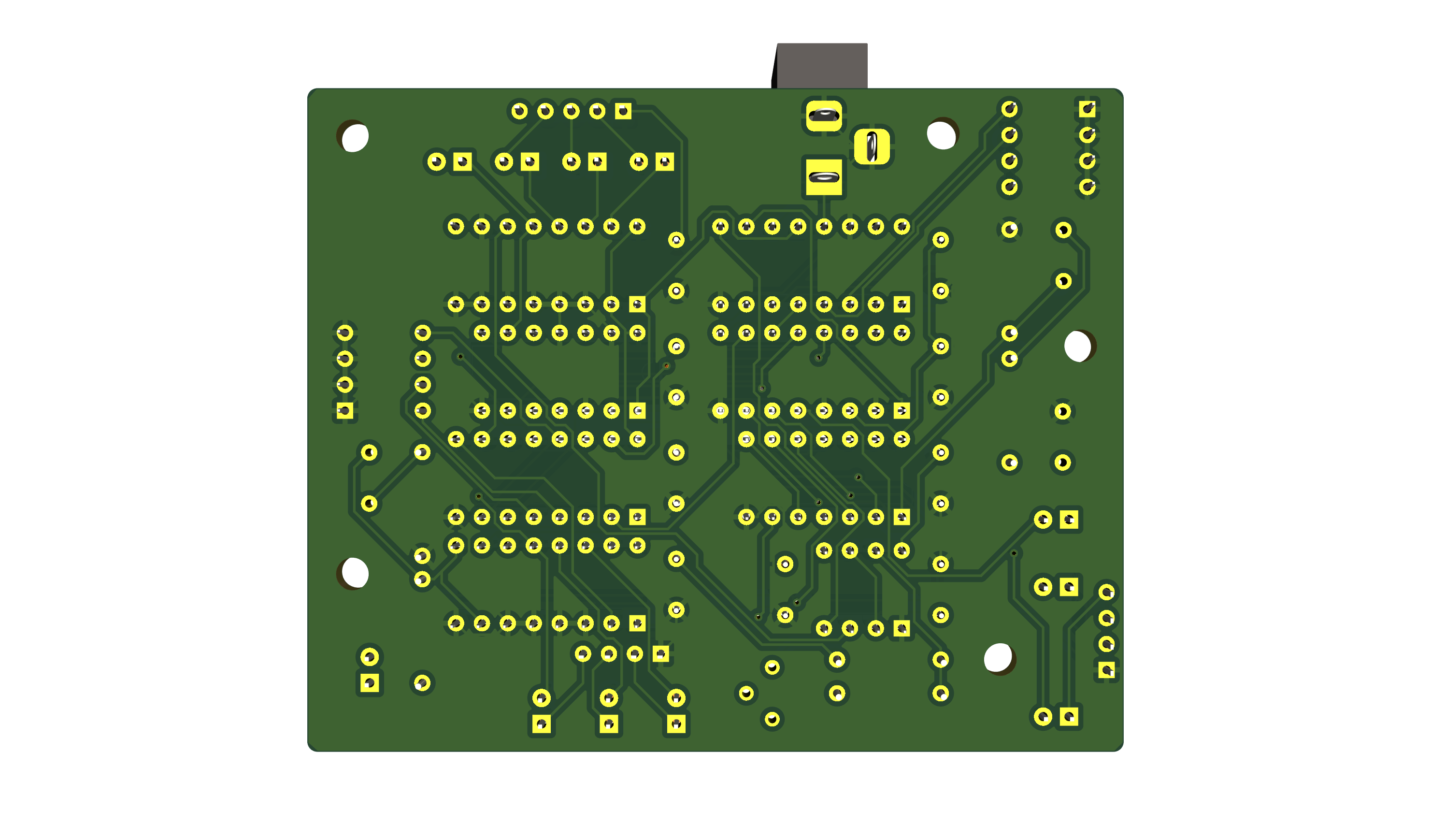
DigiMind is an open-source printed circuit board by RetroStack, from the RetroStack/BitStack-DigiMind repository on GitHub, published under the MIT licence. It is a 2-layer board of 80 × 65 mm with 44 parts on 66 nets, routed with 601 tracks and 11 vias.
It is built around the 74LS04PC, 74LS161DC and 74LS174DC, with the 74LS175PC, 74LS194PC and 74LS85DC among its other parts. Its parts include 11 diodes, 9 capacitors, 8 ICs, 6 resistors and 5 switches.


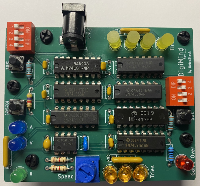
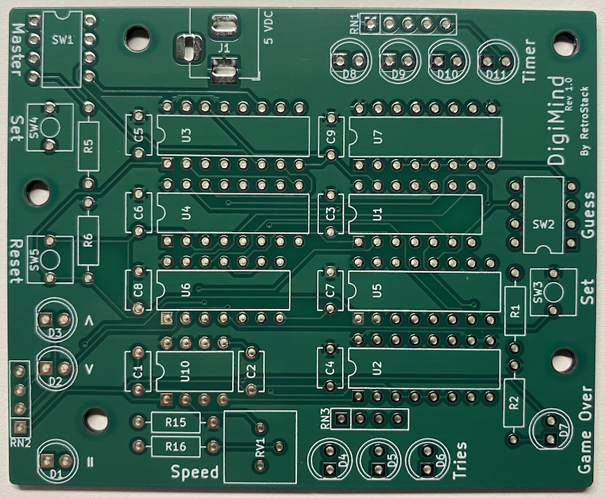
As part of an introduction in digital electronics workshop at VCF SW 2024, I prepared this design of a Masterm*nd like game to teach digital electronics.
In the "Latest" folder, you'll find the most up-to-date design files, including:
The board has been implemented using KiCAD 8. The KiCAD project files are included in this repository.
There are two players for this game:
Before starting the game, the person defining the master code hits the "Reset" button to reset the game's state. Then, they enter the code using the DIP switches labeled "Master." When completed, the "Set" button must be pushed to set the master code. After that, the master code can be cleared from the DIP switches as it has been read into the memory.
As soon as the "Set" button is pressed, a timer labeled "Timer" starts running down. When the last light turns off, the game is over (if the master code was not found). The potentiometer labeled "Speed" can increase the time a player has to guess the master code.
The guesser needs to enter a code into the DIP switch on the other side, labeled "Guess." The "Set" button right next to it can be pressed to trigger a guess attempt. Each attempt is recognized and counted up with the "Tries" lights. When reaching a binary 8, the game is over.
In either case, when the time runs out or when 8 guesses have been made and the guess was wrong, the "Game Over" light indicates the game is over. This light will turn on regardless of whether the master code was found or not (to simplify the logic). What is important is the "=" light that indicates if the guess was correct.
If the guess was wrong, the board indicates if the master code is higher or lower than the entered guess. These indicators are labeled "<" and ">".
Some decisions were made to keep the diagram somewhat readable for beginners. For example, the "Game Over" light will turn on regardless if the guess was found or not. There is also an issue when entering guesses where a bouncing of the "Set" button causes multiple guesses to register. This can be fixed by a debouncing circuit.
Below is a list of materials needed to assemble the PCB.
| Reference | Qty | Description | Footprint | Datasheet |
|---|---|---|---|---|
| C1 | 1 | 10uF | Capacitor_THT:C_Disc_D5.1mm_W3.2mm_P5.00mm | ~ |
| C2 | 1 | 0.01uF | Capacitor_THT:C_Disc_D5.1mm_W3.2mm_P5.00mm | ~ |
| C3,C4,C5,C6,C7,C8,C9 | 7 | C | Capacitor_THT:C_Disc_D5.1mm_W3.2mm_P5.00mm | ~ |
| D1 | 1 | Green | LED_THT:LED_D5.0mm | ~ |
| D2,D3 | 2 | Yellow | LED_THT:LED_D5.0mm | ~ |
| D4,D5,D6,D7,D8,D9,D10,D11 | 8 | Red | LED_THT:LED_D5.0mm | ~ |
| J1 | 1 | Barrel_Jack_Switch | Connector_BarrelJack:BarrelJack_Horizontal | ~ |
| R1,R5,R6 | 3 | R | Resistor_THT:R_Axial_DIN0207_L6.3mm_D2.5mm_P10.16mm_Horizontal | ~ |
| R2,R15,R16 | 3 | 1k | Resistor_THT:R_Axial_DIN0207_L6.3mm_D2.5mm_P10.16mm_Horizontal | ~ |
| RN1 | 1 | R_Network04 | Resistor_THT:R_Array_SIP5 | http://www.vishay.com/docs/31509/csc.pdf |
| RN2,RN3 | 2 | R_Network03 | Resistor_THT:R_Array_SIP4 | http://www.vishay.com/docs/31509/csc.pdf |
| RV1 | 1 | 1M | Potentiometer_THT:Potentiometer_Bourns_3386P_Vertical | ~ |
| SW1,SW2 | 2 | SW_DIP_x04 | Package_DIP:DIP-8_W7.62mm | ~ |
| SW3,SW4,SW5 | 3 | SW_Push | RetroStackLibrary:SW_SPST_Push | ~ |
| U2 | 1 | 74LS161 | Package_DIP:DIP-16_W7.62mm | http://www.ti.com/lit/gpn/sn74LS161 |
| U3 | 1 | 74LS174 | Package_DIP:DIP-16_W7.62mm | http://www.ti.com/lit/gpn/sn74LS174 |
| U4 | 1 | 74LS85 | Package_DIP:DIP-16_W7.62mm | http://www.ti.com/lit/gpn/sn74LS85 |
| U5 | 1 | 74LS175 | Package_DIP:DIP-16_W7.62mm | http://www.ti.com/lit/gpn/sn74LS175 |
| U6 | 1 | 74LS08 | Package_DIP:DIP-14_W7.62mm | http://www.ti.com/lit/gpn/sn74LS08 |
| U7 | 1 | 74LS194 | Package_DIP:DIP-16_W7.62mm | http://www.ti.com/lit/gpn/sn74LS194 |
| U8 | 1 | 74LS02 | http://www.ti.com/lit/gpn/sn74ls02 | |
| U10 | 1 | NA555P | Package_DIP:DIP-8_W7.62mm | http://www.ti.com/lit/ds/symlink/ne555.pdf |
To work with this KiCAD project, you'll need the RetroStack libraries for KiCAD. Please follow this link to access and install these libraries.
RetroStack is passionate about exploring and preserving the legacy of older computer systems. BitStack is a sub-project of RetroStack, focusing on education in digital electronics. My work involves creating detailed documentation and videos to share the knowledge. I am also dedicated to reviving these classic systems by reimplementing them and offering replacement parts at no cost. If you're keen on supporting this unique project, I invite you to visit my Patreon page. Your support would be immensely valuable and greatly appreciated!
This project is licensed under the MIT License - see the LICENSE file for details.
| Qty | Value | Footprint | References |
|---|---|---|---|
| 8 | Red | LED_THT:LED_D5.0mm | D4, D5, D6, D7, D8, D9, D10, D11 |
| 7 | C | Capacitor_THT:C_Disc_D5.1mm_W3.2mm_P5.00mm | C3, C4, C5, C6, C7, C8, C9 |
| 3 | 1k | Resistor_THT:R_Axial_DIN0207_L6.3mm_D2.5mm_P10.16mm_Horizontal | R2, R15, R16 |
| 3 | R | Resistor_THT:R_Axial_DIN0207_L6.3mm_D2.5mm_P10.16mm_Horizontal | R1, R5, R6 |
| 3 | SW_Push | RetroStackLibrary:SW_SPST_Push | SW3, SW4, SW5 |
| 2 | R_Network03 | Resistor_THT:R_Array_SIP4 | RN2, RN3 |
| 2 | SW_DIP_x04 | Package_DIP:DIP-8_W7.62mm | SW1, SW2 |
| 2 | Yellow | LED_THT:LED_D5.0mm | D2, D3 |
| 1 | 0.01uF | Capacitor_THT:C_Disc_D5.1mm_W3.2mm_P5.00mm | C2 |
| 1 | 1M | Potentiometer_THT:Potentiometer_Bourns_3386P_Vertical | RV1 |
| 1 | 1uF | Capacitor_THT:C_Disc_D5.1mm_W3.2mm_P5.00mm | C1 |
| 1 | 74LS04 | Package_DIP:DIP-14_W7.62mm | U1 |
| 1 | 74LS08 | Package_DIP:DIP-14_W7.62mm | U6 |
| 1 | 74LS161 | Package_DIP:DIP-16_W7.62mm | U2 |
| 1 | 74LS174 | Package_DIP:DIP-16_W7.62mm | U3 |
| 1 | 74LS175 | Package_DIP:DIP-16_W7.62mm | U5 |
| 1 | 74LS194 | Package_DIP:DIP-16_W7.62mm | U7 |
| 1 | 74LS85 | Package_DIP:DIP-16_W7.62mm | U4 |
| 1 | Barrel_Jack_Switch | Connector_BarrelJack:BarrelJack_Horizontal | J1 |
| 1 | Green | LED_THT:LED_D5.0mm | D1 |
| 1 | NA555P | Package_DIP:DIP-8_W7.62mm | U10 |
| 1 | R_Network04 | Resistor_THT:R_Array_SIP5 | RN1 |
It measures 80 × 65 mm and has 2 copper layers, 1.6 mm thick.
44 parts, built around the 74LS04PC, 74LS161DC, 74LS174DC and 74LS175PC. The full list of its parts is on this page, with links to each part's symbol and footprint where PCBKit's library has them.
From the RetroStack/BitStack-DigiMind repository on GitHub, at the commit this page was made from: the board is KiCAD/DigiMind.kicad_pcb and its schematic KiCAD/DigiMind.kicad_sch. PCBKit opens the board in the browser, with nothing to install.
Its repository publishes it under the MIT licence: you may reuse it on that licence's terms (keep the author's notice, and for a copyleft licence share your changes alike).

clemarfolly/Microdigital-TK2000
Reprodução da PCB do TK-2000 da Microdigital, clone do Micro-Professor MPF-II


electrickery/VIO_MPF_I
Extended firmware for the 6845 based video card for the Microprofessor MPF-I(b)
