2 layers31 × 21 mm
Ads816x devboard
rleh/random-pcbs
Some devboards I happend to design and wanted to share...
16 parts1CC-BY-SA-4.0
 reneayoroa/Instrumented-Insole
KiCAD Design files for an instrumented insole
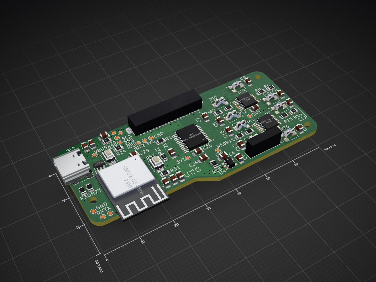
Smart insoles 2025 v1 is an open-source printed circuit board by reneayoroa, from the reneayoroa/Instrumented-Insole repository on GitHub, published under the MIT licence. It is a 4-layer board of 69.7 × 30.1 mm with 103 parts on 100 nets, routed with 1,004 tracks and 177 vias.
It is built around the ESP32-C3-MINI-1-N4, BQ24040DSQR and CD74HC4067M96, with the ME6211C33M5G-N, USBLC6-2SC6 and TC33X-2-302E among its other parts. Its parts include 29 capacitors, 23 resistors, 9 ICs, 4 diodes and 3 connectors. It belongs with the ESP32 and RISC-V boards of this library.


KiCAD Design files for an instrumented insole
| Qty | Value | Footprint | References |
|---|---|---|---|
| 16 | TestPoint_Alt | TestPoint:TestPoint_Pad_D1.0mm | TP1, TP2, TP3, TP4, TP5, TP6, TP7, TP8, TP9, TP10, TP11, TP12, TP13, TP14, TP15, TP16 |
| 12 | 1uF | Capacitor_SMD:C_0805_2012Metric_Pad1.18x1.45mm_HandSolder | C3, C4, C5, C14, C16, C17, C18, C19, C21, C22, C23, C26 |
| 8 | 10nF | Capacitor_SMD:C_0805_2012Metric_Pad1.18x1.45mm_HandSolder | C6, C7, C8, C9, C10, C11, C12, C13 |
| 8 | TC33X-2-302E | 3x3_TrimPot:TRIM_TC33X-2-302E | PT0, PT1, PT2, PT3, PT4, PT5, PT6, PT7 |
| 7 | 100k | Resistor_SMD:R_0805_2012Metric | R3, R4, R6, R10, R11, R14, R15 |
| 5 | 0.1uF | Capacitor_SMD:C_0805_2012Metric_Pad1.18x1.45mm_HandSolder | C1, C2, C20, C27, C29 |
| 4 | 10k | Resistor_SMD:R_0805_2012Metric | R22, R24, R29, R31 |
| 3 | 1.5k | Resistor_SMD:R_0805_2012Metric_Pad1.20x1.40mm_HandSolder | R20, R21, R28 |
| 3 | 100nF | Capacitor_SMD:C_0805_2012Metric_Pad1.18x1.45mm_HandSolder | C15, C24, C25 |
| 3 | LED | LED_SMD:LED_0805_2012Metric | D1, D2, D3 |
| 3 | MountingHole | MountingHole:MountingHole_2.1mm | H1, H2, H3 |
| 2 | 5.1k 1% | Resistor_SMD:R_0805_2012Metric | R23, R30 |
| 2 | MCP6004-I_ST | MCP6004_I_ST:custom | U8, U9 |
| 2 | SolderJumper_2_Open | Jumper:SolderJumper-2_P1.3mm_Open_RoundedPad1.0x1.5mm | JP1, JP2 |
| 1 | 1.1k | Resistor_SMD:R_0805_2012Metric_Pad1.20x1.40mm_HandSolder | R13 |
| 1 | 100k | Resistor_SMD:R_0805_2012Metric_Pad1.20x1.40mm_HandSolder | R8 |
| 1 | 10k | Resistor_SMD:R_0805_2012Metric_Pad1.20x1.40mm_HandSolder | R26 |
| 1 | 10k | Resistor_SMD:R_Array_Concave_4x0603 | RN1 |
| 1 | 10uF | Capacitor_SMD:C_0805_2012Metric_Pad1.18x1.45mm_HandSolder | C28 |
| 1 | 1k | Resistor_SMD:R_0805_2012Metric_Pad1.20x1.40mm_HandSolder | R25 |
| 1 | 2.0k | Resistor_SMD:R_0805_2012Metric_Pad1.20x1.40mm_HandSolder | R27 |
| 1 | 3.5k | Resistor_SMD:R_0805_2012Metric | R18 |
| 1 | BOOT | Button_Switch_SMD:SW_Push_SPST_NO_Alps_SKRK | SW2 |
| 1 | BQ24040DSQR | BQ24040DSQR:SON40P200X200X80-11N | U7 |
| 1 | CD74HC4067M96 | Package_SO:TSSOP-24_6.1x7.8mm_P0.65mm | U2 |
| 1 | Conn_01x20 | Connector_Samtec_MicroMate:Samtec_T1M-20-X-S-RA_1x20-1MP_P1.0mm_Terminal_Horizontal | J1 |
| 1 | ESP32-C3-MINI-1-N4 | ESP32-C3-MINI-1-N4:XCVR_ESP32-C3-MINI-1-N4 | U5 |
| 1 | FDN306P | FDN306P:SSOT-3 | Q2 |
| 1 | LSM6DSO32TR | LDM6S032TR:XDCR_LSM6DSO32TR | U3 |
| 1 | ME6211C33M5 | Package_TO_SOT_SMD:SOT-23-5 | U1 |
| 1 | R | Resistor_SMD:R_0805_2012Metric | R1 |
| 1 | RESET | Button_Switch_SMD:SW_Push_SPST_NO_Alps_SKRK | SW1 |
| 1 | S2B-PH-SM4-TB_LF__SN_ | JST-PH2-2.00MM-SMD-HORIZONTAL:JST_S2B-PH-SM4-TB_LF__SN_ | J4 |
| 1 | SS24 | Diode_SMD:D_SMA | D5 |
| 1 | SW_Nidec_CAS-120A1 | Button_Switch_THT:SW_Slide-03_Wuerth-WS-SLTV_10x2.5x6.4_P2.54mm | SW3 |
| 1 | Thermistor_NTC | thermistor_10k_NTC_solderPad:thermistor_10k_NTC_SolderPad | TH1 |
| 1 | USBLC6-2SC6 | USBLC6-2SC6:SOT95P280X145-6N | IC1 |
| 1 | USB_C_Receptacle_USB2.0_16P | USB_C_Receptacle_16P_SMD_pins_THT_mech:USB_C_Receptacle_GCT_USB4105-xx-A_16P_TopMnt_Horizontal | J2 |
| 1 | ~ | ADM8829:SOT95P280X145-6N | U4 |
rleh/random-pcbs
Some devboards I happend to design and wanted to share...


wei756/TastyMotionTracker
TastyMotionTracker-SlimeVR PCB SMT Project

MukeshSethy/micromouse-runner
This is my repo for the first version of full size micromouse development.


electromotif208/pcb-portfolio
👨💻 Electronics Engineer 📺 YouTube: ELECTROMOTIF 🔧 Tools: KiCad, EasyEDA 📡 Domains: Power Supply, ESP32, IoT, Embedded Hardware

nguyenmihn/Library-Custom-Kicad
A professional documentation template for KiCad projects inspired by industrial engineering document standards.

It measures 69.7 × 30.1 mm and has 4 copper layers, 1.58 mm thick.
103 parts, built around the ESP32-C3-MINI-1-N4, BQ24040DSQR, CD74HC4067M96 and ME6211C33M5G-N. The full list of its parts is on this page, with links to each part's symbol and footprint where PCBKit's library has them.
From the reneayoroa/Instrumented-Insole repository on GitHub, at the commit this page was made from: the board is Design_Files/Smart_Insole_2025/Smart_insoles_2025_v1/Smart_insoles_2025_v1.kicad_pcb and its schematic Design_Files/AFE_p1/AFE_p1.kicad_sch. PCBKit opens the board in the browser, with nothing to install.
Its repository publishes it under the MIT licence: you may reuse it on that licence's terms (keep the author's notice, and for a copyleft licence share your changes alike).