2 layers65 × 56.5 mm

 regymm/ymmepm3
Altera MAX II EPM1270 development board and more
Ymmepm is an open-source printed circuit board by regymm, from the regymm/ymmepm repository on GitHub, published under the GPL-3.0 licence. It is a 2-layer board of 100 × 100 mm with 165 parts on 136 nets, routed with 1,739 tracks and 200 vias.
It is built around the EPM1270T144C3 and EPM570T100C3. Its parts include 35 resistors, 35 connectors, 18 capacitors, 3 diodes and 2 ICs. It belongs with the FPGA and CPLD boards of this library.


Board with Altera MAX II EPM1270. With a pluggable 480x320 LCD screen and a matrix keyboard, it work well as a handheld serial terminal. Video.
Gallery
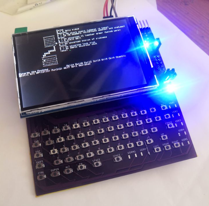
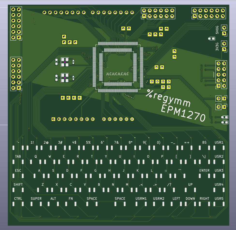
The terminal
rtl/lcd_terminal.v
Due to the scares resource of the EPM1270, the terminal supports only basic cursor movement and clear VT100(^[[X) sequences, others are detected and ignored. Have to put character pixel lists into slow UFM, so only up to 19200 baud rate. In case of Linux, bash and commands like ls work. nano won't display correctly and the editor that works is ed or my ymedit. CTS flow control is utilized to avoid losing chars when clearing full screen. (so need to connect 5 wires to use: 5V0, GND, rx, tx, cts)
The keyboard
rtl/uart_keyboard.v
Currently support only single-byte chars, arrow keys won't work. In code UP and RIGHT are used as extra SHIFT and CTRL.
Covering keyboard with high-temperature yellow tape will significantly improve type feeling.
Design
Simple is the main concern ... or not?
Single 3V3, or single 5V0 with ASM1117 to 3V3.
Right two PMODs directly connected to CPLD. Left 2 PMODs share the Arduino pins(these literally give the plugged LCD screen a PMOD interface). Spare IOs scattered here and there.
1 power LED, 2 user LEDs, 2 user jumpers. 2 oscillators. A strange matrix keyboard.
For the simplest verification, only the CPLD, power pins, and JTAG pins are needed. Even caps on the back can be left empty.
Footprint is compatible with EPM1270/570/240 TQFP144/100, but certainly the full terminal can only fit into EPM1270(~ 90% logic elements used).
Bugs
5V is not connected to the Arduino pin. Fly a wire from ASM1117 if using 5V LCD screen.
JTAG header pins should be soldered on back of the board.
Still some tiny problems in the supported VT100 controls. But if the fix is paid in extra logic elements, I have to consider.
| Qty | Value | Footprint | References |
|---|---|---|---|
| 69 | KEY | ymm:SW_Push_SPST_NO_Alps_SKRK_BARE | -1, ,1, ;1, .0, .1, .2, .3, .4, .5, .6, .7, .8, .9, .10, '1, /1 +53 |
| 35 | R | Resistor_SMD:R_0603_1608Metric_Pad0.98x0.95mm_HandSolder | R1, R2, R10, R11, R12, R13, R14, R15, R16, R17, R18, R19, R20, R21, R22, R23 +19 |
| 25 | HOLE | ymm:PinHeader_1x01_P2.54mm_Vertical_BARE | J16, J17, J18, J19, J20, J21, J22, J23, J24, J25, J26, J27, J28, J29, J30, J31 +9 |
| 16 | C | Capacitor_SMD:C_0603_1608Metric_Pad1.08x0.95mm_HandSolder | C1, C2, C3, C4, C5, C6, C7, C8, C9, C10, C11, C12, C13, C14, C15, C18 |
| 3 | LED | LED_SMD:LED_0603_1608Metric_Pad1.05x0.95mm_HandSolder | D2, D3, D4 |
| 2 | C0402 | Capacitor_SMD:C_0402_1005Metric_Pad0.74x0.62mm_HandSolder | C16, C19 |
| 2 | Just an OSC | Oscillator:Oscillator_SMD_SeikoEpson_SG8002CE-4Pin_3.2x2.5mm | X1, X3 |
| 2 | PMOD1 | Connector_PinHeader_2.54mm:PinHeader_2x06_P2.54mm_Vertical | J2, J15 |
| 1 | 3V3G | Connector_PinHeader_2.54mm:PinHeader_1x02_P2.54mm_Vertical | J9 |
| 1 | 5V0G | Connector_PinHeader_2.54mm:PinHeader_1x02_P2.54mm_Vertical | J6 |
| 1 | Arduino LCD | Module:Arduino_UNO_R2 | J10 |
| 1 | EPM1270T144 | Package_QFP:LQFP-144_20x20mm_P0.5mm | U1 |
| 1 | EPM570T100 | Package_QFP:LQFP-100_14x14mm_P0.5mm | U2 |
| 1 | JP1 | Connector_PinHeader_2.54mm:PinHeader_1x02_P2.54mm_Vertical | J13 |
| 1 | JP2 | Connector_PinHeader_2.54mm:PinHeader_1x02_P2.54mm_Vertical | J14 |
| 1 | JTAG | Connector_PinSocket_2.54mm:PinSocket_2x05_P2.54mm_Vertical | J1 |
| 1 | PMOD2 | Connector_PinHeader_2.54mm:PinHeader_2x06_P2.54mm_Vertical | J3 |
| 1 | PMOD3 | Connector_PinHeader_2.54mm:PinHeader_2x06_P2.54mm_Vertical | J4 |
| 1 | SOT-223_AMS1117-3.3 | lc_lib:SOT-223 | VR1 |

RWeick/NDS-Codebreaker
The full schematic, gerbers, and flash rom dump of the Nintendo DS Codebreaker


viuhimciuc/coolgirl-nes-multicart
Ultimate multigame cartridge for Nintendo Entertainment System (NES)


peej/lumberjack-keyboard
5x12 ortholinear through-hole component keyboard PCB for standard 60% cases


It measures 100 × 100 mm and has 2 copper layers, 1.6 mm thick.
165 parts, built around the EPM1270T144C3 and EPM570T100C3. The full list of its parts is on this page, with links to each part's symbol and footprint where PCBKit's library has them.
From the regymm/ymmepm repository on GitHub, at the commit this page was made from: the board is board/ymmepm.kicad_pcb. PCBKit opens the board in the browser, with nothing to install.
Its repository publishes it under the GPL-3.0 licence: you may reuse it on that licence's terms (keep the author's notice, and for a copyleft licence share your changes alike).