2 layers45.8 × 60 mm
RD Deauther
rdhrobotics/RF-Hunter
A compact, standalone wireless security research device. Three tools in one — RF jammer, Wi-Fi deauther, and captive portal
55 parts

 rdhrobotics/RF-Hunter
A compact, standalone wireless security research device. Three tools in one — RF jammer, Wi-Fi deauther, and captive portal
0.96 OLED is an open-source printed circuit board by rdhrobotics, from the rdhrobotics/RF-Hunter repository on GitHub. It is a 2-layer board of 30 × 30 mm with 64 parts on 33 nets, routed with 191 tracks and 57 vias.
Its parts include 10 capacitors, 9 resistors, 3 ICs, 3 switches and 1 diode. It belongs with the radio and wireless and lEDs and displays boards of this library.
ESP8266 + nRF24L01 · OLED Display · Open Source Hardware & Firmware

 [blocked]
 [blocked]
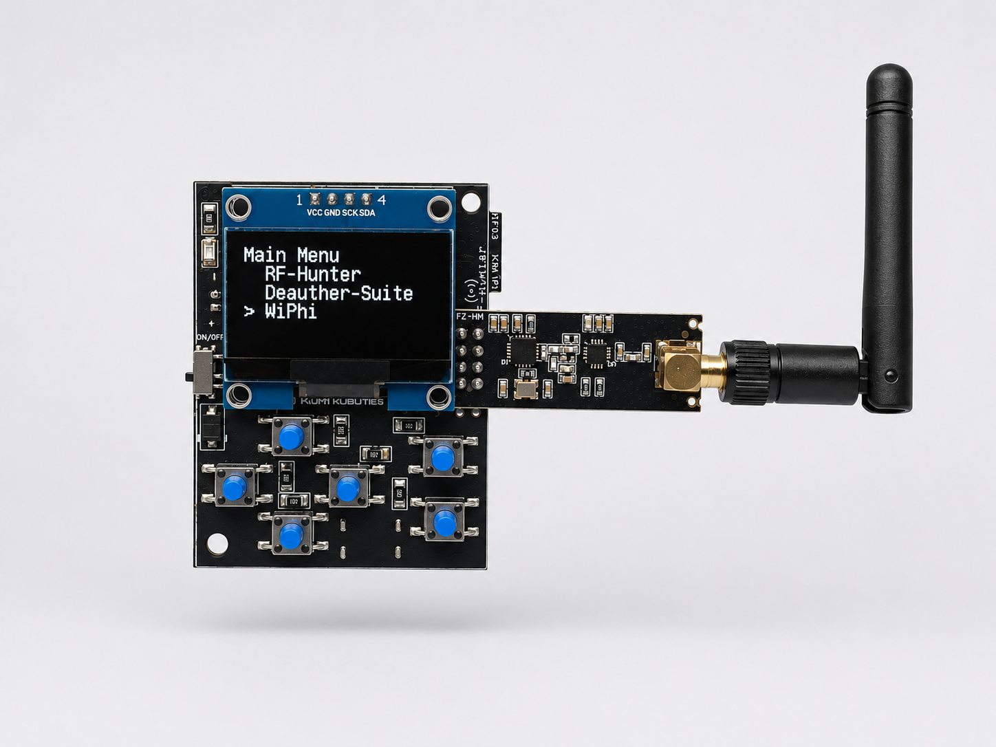
A compact, standalone wireless security research device. Three tools in one — RF jammer, Wi-Fi deauther, and captive portal testbed — controlled from a 128×64 OLED display and 6-button keypad. No laptop required.
If you want to skip the build and get straight to learning:
→ Buy RF-Hunter at rdhrobotics.in
Assembled, tested, and shipped. Includes quick-start card.
The RF-Hunter is a hardware platform for studying 2.4 GHz wireless security concepts hands-on. It runs three independent research modules from a unified launcher UI:
| Module | Description |
|---|---|
| RF-Hunter | nRF24 constant carrier jammer. BLE + all 2.4 GHz or Wi-Fi channels only.. |
| Deauther Suite | spacehuhn esp8266_deauther engine. Scan, select, deauth, beacon flood, probe attack. |
| WiPhi | Deauth + EvilTwin + captive portal credential harvester with EEPROM vault. |
| RF Chat | (bonus sketch) Point-to-point text chat over raw nRF24 radio. |
Everything is navigated from the OLED + keypad, or remotely via the built-in web admin panel at 192.168.4.1.
| Component | Part |
|---|---|
| MCU | ESP8266 (80/160 MHz, 2.4 GHz Wi-Fi) |
| RF module | nRF24L01+ PA+LNA |
| Display | SH1106 128×64 OLED (I²C) |
| Input | 6-button ADC keypad (voltage divider) |
| Storage | EEPROM — 5-slot credential vault, persists across reboots |
nRF24L01   CE  → GPIO16
           CSN → GPIO15

SH1106     SDA → GPIO4
SCL → GPIO5#define BTN_UP 135
#define BTN_DOWN 579
#define BTN_LEFT 426
#define BTN_RIGHT 634
#define BTN_ENTER 729
#define BTN_BACK 687Adjust values to match your resistor network.
RF24, ESP8266WiFi, DNSServer, ESP8266WebServer, SH1106Wire (ESP8266-OLED), ADCButton, ArduinoJson v5git clone https://github.com/rdhrobotics/RF-Hunter.gitOpen RFHunter/RFHunter.ino in Arduino IDE. Select Generic ESP8266 (Deauther) as the board. Flash at 115200 baud.
RF-Hunter/
├── RFHunter/
│   └── RFHunter.ino        ← main sketch (all three tools)
│
├── Hardware Source/
│   ├── RD_Deauther.pdf // schematic
│ └── RD_Deauther.kicad_pro // Kicad Project┌─────────────────┐
│ Main Menu │ ← Launcher
│ > RF-Hunter │
│ Deauther │
│ WiPhi │
└─────────────────┘
│
├── RF-Hunter → select mode → running (BACK to stop)
├── Deauther → full spacehuhn DisplayUI
└── WiPhi → scan → select AP → attack → captured PWHold BACK for 5 seconds from any mode to return to the launcher main menu.
The launcher uses a mode table — drop in a new attack without touching the state machine.
Step 1 — declare your functions:
void myMode_init();
void myMode_tick();
Step 2 — add a row to the table:
const NrfMode NRF_MODES[] = {
    { "BLE & All 2.4GHz", nrfAttackAllInit,  nrfAttackAllTick,  true },
    { "Just Wi-Fi",       nrfAttackWiFiInit, nrfAttackWiFiTick, true },
    { "My New Mode",      myMode_init,       myMode_tick,       false }, // ← add here
};
Step 3 — write the functions anywhere below. Done.
WiPhi saves captured credentials to EEPROM and survives power cycles.
Addr 0        Magic byte (0xAB) — detects first boot
Addr 1–485    5 slots × (1 valid flag + 32 SSID + 64 PW)

WiPhi vault (in Launcher, offset to avoid deauther collision):
Addr 2000     Magic byte (0xBC)
Addr 2001+    Same slot layout × 5
Browse and delete saved passwords from the OLED: Main Menu → Saved Passwords.
While WiPhi is running, connect to:
SSID:     WiPhi_34732
Password: d347h320
URL:      http://192.168.4.1/admin
The web UI and OLED run simultaneously — control from either.
This project is fully open source — firmware and hardware both.
| License | |
|---|---|
| Firmware | MIT |
| Hardware (schematic, BOM) | CERN OHL v2 Permissive |
The Deauther Suite module uses the spacehuhn/esp8266_deauther engine, which is also MIT licensed.
Pull requests welcome. See CONTRIBUTING.md for guidelines.
This device is built for authorized security research, CTF competitions, and educational use.
by @rdhrobotics — open hardware for security education.
| Qty | Value | Footprint | References |
|---|---|---|---|
| 20 | buzzardLabel | , , , , , , , , , , , , , , , +4 | |
| 7 | 10k | e-radionica.com footprinti:0603R | R1, R2, R3, R4, R6, R7, R8 |
| 4 | 2u2 | e-radionica.com footprinti:0603C | C1, C2, C5, C8 |
| 4 | HOLE_3.2mm | e-radionica.com footprinti:HOLE_3.2mm | H1, H2, H3, H4 |
| 3 | 10u | e-radionica.com footprinti:1206C | C3, C7, C9 |
| 2 | 100n | e-radionica.com footprinti:0603C | C6, C10 |
| 2 | LOGO | Soldered Graphics:Logo-Front-easyC-5mm | G***, G*** |
| 2 | SMD-JUMPER-CONNECTED_TRACE_SLODERMASK | e-radionica.com footprinti:SMD-JUMPER-CONNECTED_TRACE_SLODERMASK | JP2, JP4 |
| 2 | SMD_JUMPER | e-radionica.com footprinti:SMD_JUMPER | JP5, JP6 |
| 2 | SMD_JUMPER_3_PAD_TRACE | e-radionica.com footprinti:SMD_JUMPER_3_PAD_TRACE | JP1, JP3 |
| 2 | easyC-SMD | e-radionica.com footprinti:easyC-connector | K1, K2 |
| 1 | 1u | e-radionica.com footprinti:0603C | C4 |
| 1 | 2k2 | e-radionica.com footprinti:0402R | R5 |
| 1 | 390k | e-radionica.com footprinti:0603R | R9 |
| 1 | FIDUCIAL | e-radionica.com footprinti:FIDUCIAL_23 | FD1 |
| 1 | HEADER_MALE_4X1 | e-radionica.com footprinti:HEADER_MALE_4X1 | K3 |
| 1 | LOGO | Soldered Graphics:Logo-Back-SolderedVERTICAL-6mm | G*** |
| 1 | LOGO | Soldered Graphics:Logo-Front-Soldered-3mm | G*** |
| 1 | LOGO | Soldered Graphics:Logo-Front-OSH-3.5mm | G*** |
| 1 | NMOS-DUAL | e-radionica.com footprinti:SOT-363 | U1 |
| 1 | OLED_GME12864_30p | e-radionica.com footprinti:OLED_GME128x64_30p | U3 |
| 1 | SE5218 | e-radionica.com footprinti:SOT-23-5 | U2 |
| 1 | purple | e-radionica.com footprinti:0402LED | D1 |
The 62 most common of 64 parts.
rdhrobotics/RF-Hunter
A compact, standalone wireless security research device. Three tools in one — RF jammer, Wi-Fi deauther, and captive portal

hackclub/OnBoard
💡 Join 1,000 teenagers and make your first PCB with a $100 grant!

drandyhaas/KiCadRoutingTools
A set of Python/Rust tools to aid routing in KiCad

BlueSCSI/BlueSCSI-v2
BlueSCSI v2/Ultra - an open source, open hardware, SCSI emulator using the Pi Pico PR2040 and Pico 2 RP2350


PyrooL/Alpha
A 28-key semi-ortholinear mechanical keyboard designed by PyroL

ugcs/ddc
Drone Show Software is software designed for drone shows, allowing flight path planning as well as control of dozens of drones simultaneously in a synchronized manner.

It measures 30 × 30 mm and has 2 copper layers, 1.6 mm thick.
64 parts. The full list of its parts is on this page, with links to each part's symbol and footprint where PCBKit's library has them.
From the rdhrobotics/RF-Hunter repository on GitHub, at the commit this page was made from: the board is Hardware Source/Ref_Resource/Display-OLED-I2C-White-0.96-hardware-design-main/Display-OLED-I2C-White-0.96-hardware-design-main/CAD/V1.3.0/0.96_OLED.kicad_pcb and its schematic Hardware Source/RD_Deauther.kicad_sch. PCBKit opens the board in the browser, with nothing to install.
Its repository states no licence, so its author keeps all rights: ask rdhrobotics before reusing the design.