
2 layers

 ravinrabbid/BuildGun1
Drop-in replacement for the electronics of the Satisfactory Build Gun replica.
BuildGun is an open-source printed circuit board by ravinrabbid, from the ravinrabbid/BuildGun repository on GitHub, published under the MIT licence. It is a 2-layer board of 98 × 27 mm with 36 parts on 21 nets, routed with 213 tracks and 6 vias.
It is built around the COM-09032 and WS2812B. Its parts include 10 diodes, 3 resistors, 3 connectors, 2 capacitors and 2 ICs. It belongs with the RP2040 boards of this library.
Drop-in replacement for the electronics of the Satisfactory Build Gun replica. Also works for the 3D printed DIY variant. Built around the XIAO RP240.
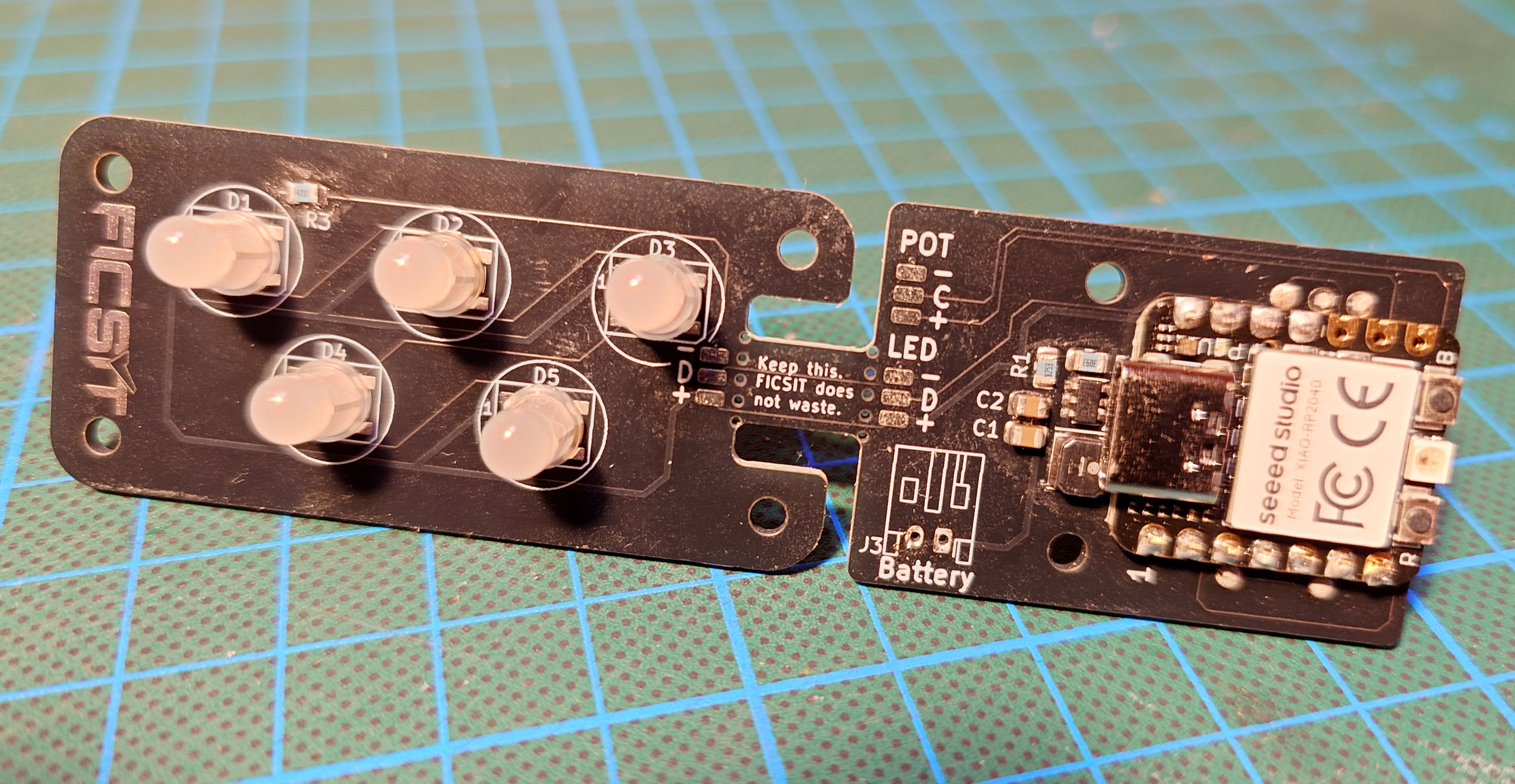
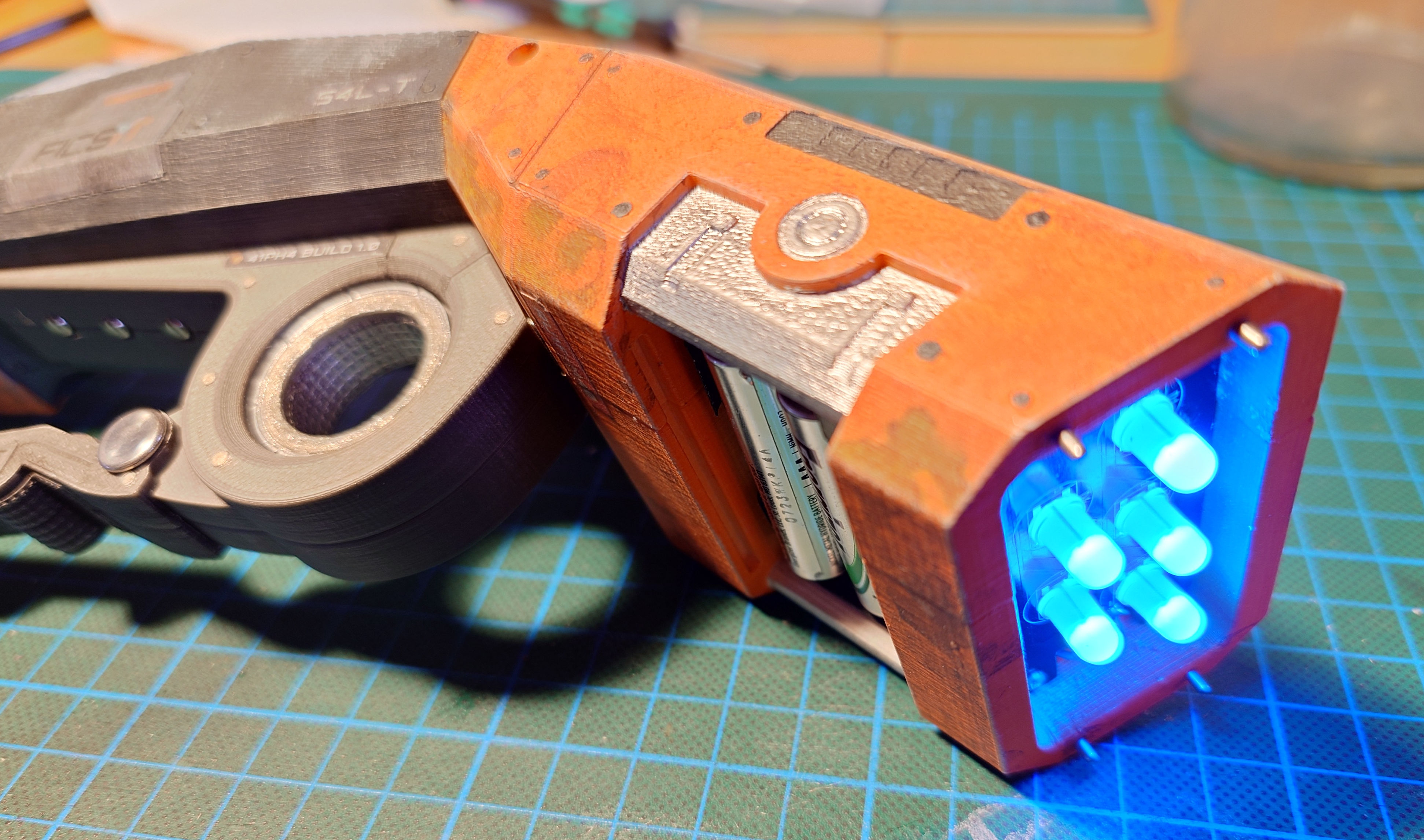
| Reference | Description | Notes |
|---|---|---|
| U1 | XIAO RP2040 | |
| U2 | MCP1640T-I/CHY Boost Regulator | |
| U3 | PS4 thumb stick | other sticks will probably work too |
| D1-D5 | WS2812B SMD LEDs | alternatively fit D6-D10 |
| D6-D10 | PL9832 5mm LEDs | alternatively fit D1-D5 |
| L1 | NRS4018T4R7MDGJ 4.7µH inductor | |
| R1 | 825kΩ 0801 resistor | |
| R2 | 309kΩ 0801 resistor | |
| R3 | 470Ω 0801 resistor | |
| C1, C2 | 10uF 0805 capacitor |
| Qty | Value | Footprint | References |
|---|---|---|---|
| 5 | APA-106-F5 | Library:LED_D5.0mm-4_RGB_stackable | D6, D7, D8, D9, D10 |
| 5 | WS2812B | Library:LED_WS2812B_PLCC4_5.0x5.0mm_P3.2mm_stackable | D1, D2, D3, D4, D5 |
| 3 | GND | Connector_Wire:SolderWirePad_1x01_SMD_1x2mm | TP3, TP4, TP9 |
| 2 | 10µF | Capacitor_SMD:C_0805_2012Metric | C1, C2 |
| 2 | LED Data | Connector_Wire:SolderWirePad_1x01_SMD_1x2mm | TP5, TP6 |
| 2 | VAL** | Library:mouse-bite-2mm-slot | mouse-bite-2mm-slot, mouse-bite-2mm-slot |
| 2 | VCC | Connector_Wire:SolderWirePad_1x01_SMD_1x2mm | TP1, TP2 |
| 1 | 309k | Resistor_SMD:R_0805_2012Metric | R2 |
| 1 | 4.7µH | Inductor_SMD:L_Taiyo-Yuden_NR-40xx | L1 |
| 1 | 470 | Resistor_SMD:R_0805_2012Metric | R3 |
| 1 | 825k | Resistor_SMD:R_0805_2012Metric | R1 |
| 1 | Battery | Connector_JST:JST_PH_S2B-PH-K_1x02_P2.00mm_Horizontal | J3 |
| 1 | COM-09032 | Library:PS4_joystick | U3 |
| 1 | Conn_01x04 | Connector_PinHeader_2.54mm:PinHeader_1x04_P2.54mm_Vertical | J4 |
| 1 | Conn_01x07 | Connector_PinHeader_2.54mm:PinHeader_1x07_P2.54mm_Vertical | J1 |
| 1 | MCP1640x-xCHY | Package_TO_SOT_SMD:SOT-23-6 | U2 |
| 1 | POT | Connector_Wire:SolderWirePad_1x01_SMD_1x2mm | TP8 |
| 1 | POT Enable | Connector_Wire:SolderWirePad_1x01_SMD_1x2mm | TP7 |
The 32 most common of 36 parts.

FishyG/ProjetFinalGI
Git pour le projet final en GI. Contient l'activité 1 et 3

LimesOrLemons/Macropaduno
An ESP32-S3 handheld controller with a custom PCB and 3D-printed enclosure for numerous programmable functions.

xxdamlaxx/DroidVR
A DIY VR controller ecosystem — open-source hardware and firmware for SteamVR-compatible motion controllers.

FundamentalFrequency/LMN-3-ECAD
Electrical CAD Files for the LMN-3 Project


Hex-4/glyph
[ a custom split keyboard for portably and comfortably interfacing with computing systems ]
It measures 98 × 27 mm and has 2 copper layers, 1.6 mm thick.
36 parts, built around the COM-09032 and WS2812B. The full list of its parts is on this page, with links to each part's symbol and footprint where PCBKit's library has them.
From the ravinrabbid/BuildGun repository on GitHub, at the commit this page was made from: the board is pcb/BuildGun.kicad_pcb and its schematic pcb/BuildGun.kicad_sch. PCBKit opens the board in the browser, with nothing to install.
Its repository publishes it under the MIT licence: you may reuse it on that licence's terms (keep the author's notice, and for a copyleft licence share your changes alike).