2 layers144.1 × 108.1 mm

 ra0sms/universal_control_console
Control console for any types of antenna's switches
Wired console k9ay is an open-source printed circuit board by ra0sms, from the ra0sms/universal_control_console repository on GitHub, published under the MIT licence. It is a 2-layer board of 100 × 70 mm with 115 parts on 158 nets, routed with 1,197 tracks and 187 vias.
It is built around the STM32G030K8T6, CH340C and UDN2981A-T, with the 74HC595, ULN2003A and USBLC6-4 among its other parts. Its parts include 37 capacitors, 36 resistors, 12 ICs, 11 connectors and 8 fuses. It belongs with the radio and wireless boards and the STM32 boards of this library.


The device can control any type of antenna switches. It has 8 independent programmable outputs and also can control my version of receiving antenna K9AY.
More information (in Russian, but Translate button still works) - https://ra0sms.com/ucc/
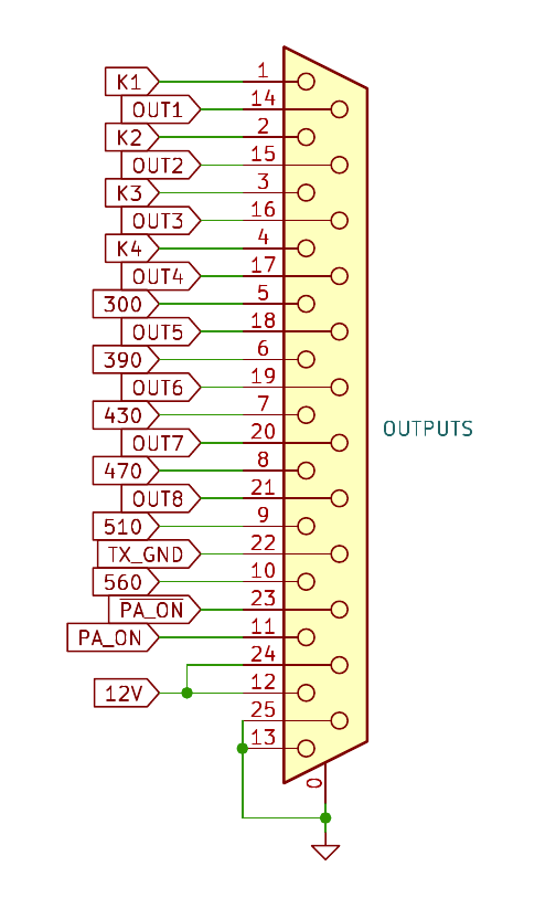
| DB25 pins | Description |
|---|---|
| 1 | K1 - open collector out for K9AY direction control |
| 2 | K2 - open collector out for K9AY direction control |
| 3 | K3 - open collector out for K9AY direction control |
| 4 | K4 - open collector out for K9AY direction control |
| 5 | 300 - open collector out for K9AY load control |
| 6 | 390 - open collector out for K9AY load control |
| 7 | 430 - open collector out for K9AY load control |
| 8 | 470 - open collector out for K9AY load control |
| 9 | 510 - open collector out for K9AY load control |
| 10 | 560 - open collector out for K9AY load control |
| 11 | PA_ON - open collector out for K9AY preamplifier control |
| 12 | 12V - output voltage (goes directly from power supply connector with the diode protection) |
| 13 | GND - Ground |
| 14 | OUT1 - First programmable output (when activated, has 12V out with fuse protection) |
| 15 | OUT2 - Second programmable output (when activated, has 12V out with fuse protection) |
| 16 | OUT3 - Third programmable output (when activated, has 12V out with fuse protection) |
| 17 | OUT4 - Fourth programmable output (when activated, has 12V out with fuse protection) |
| 18 | OUT5 - Fifth programmable output (when activated, has 12V out with fuse protection) |
| 19 | OUT6 - Sixth programmable output (when activated, has 12V out with fuse protection) |
| 20 | OUT7 - Seventh programmable output (when activated, has 12V out with fuse protection) |
| 21 | OUT8 - Eighth programmable output (when activated, has 12V out with fuse protection) |
| 22 | TX_GND - when PTT activated, has connection to ground |
| 23 | $\overline{\text{PAON}}$ - when Preamp button pressed, has 12V out without any protection |
| 24 | 12V - output voltage (goes directly from power supply connector with the diode protection) |
| 25 | GND - Ground |
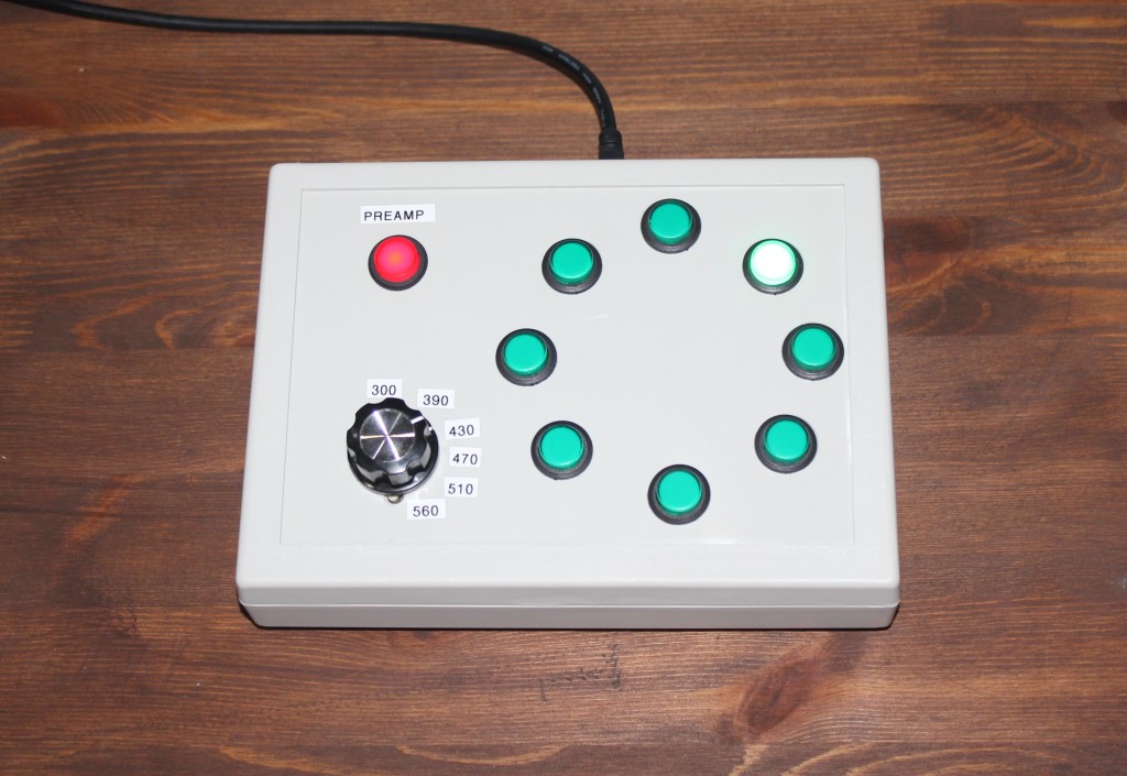
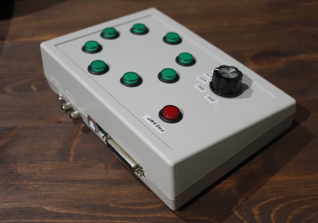
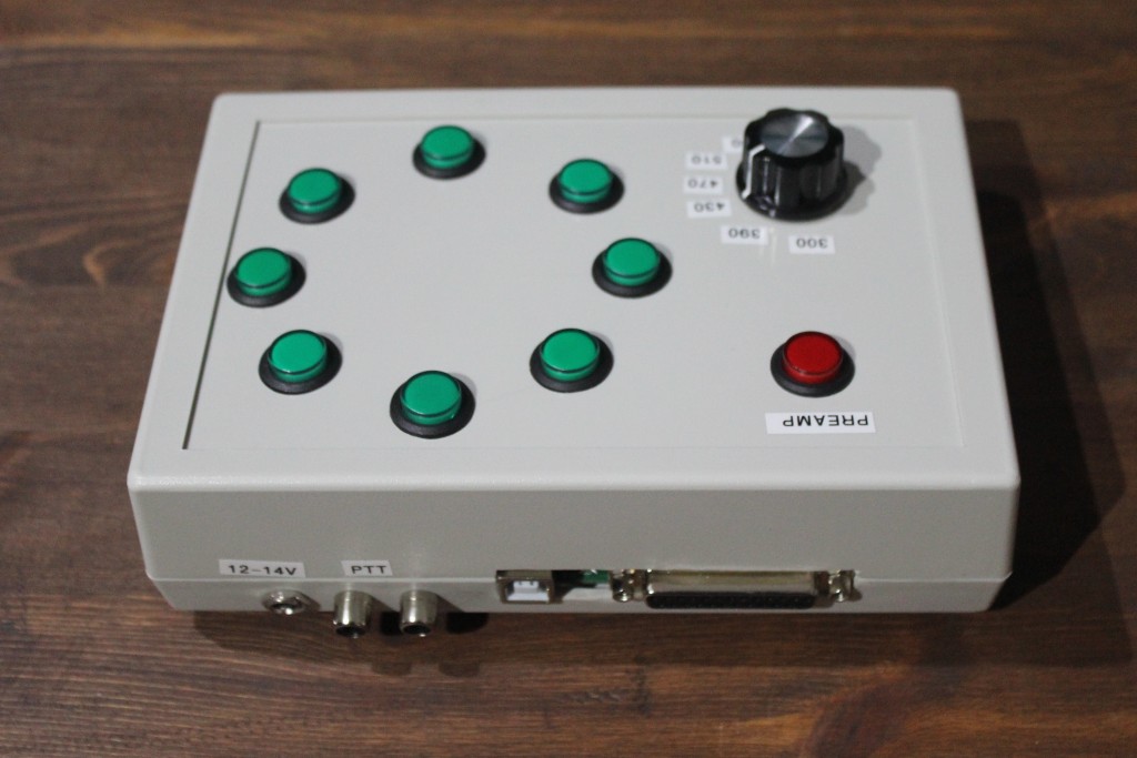
You can choose outputs which will be activated when you push the buttons. Just connect USB to PC, choose com port and click Connect button.
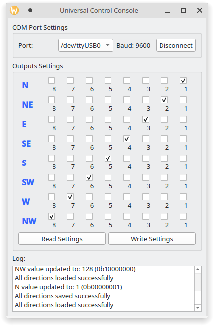
UCC also can work with hamradio software, which use Yaesu rotator protocol. UCC can emulate a rotation at a given angle. You can use it with any supported software. For example PST Rotator AZ and DXLog.
| Qty | Value | Footprint | References |
|---|---|---|---|
| 21 | 100n | Capacitor_SMD:C_1206_3216Metric_Pad1.33x1.80mm_HandSolder | C1, C2, C3, C4, C10, C11, C12, C13, C14, C15, C16, C23, C25, C33, C34, C37 +5 |
| 19 | 1k | Resistor_SMD:R_1206_3216Metric | R1, R2, R3, R4, R5, R6, R10, R11, R12, R13, R14, R15, R21, R31, R34, R36 +3 |
| 9 | 82 | Resistor_SMD:R_1206_3216Metric | R22, R23, R24, R25, R26, R27, R28, R29, R30 |
| 8 | 100n | Capacitor_SMD:C_1206_3216Metric | C19, C20, C21, C24, C28, C29, C30, C31 |
| 8 | Fuse | Resistor_SMD:R_1206_3216Metric | F1, F2, F3, F4, F5, F6, F7, F8 |
| 5 | 10u | Capacitor_SMD:C_1206_3216Metric_Pad1.33x1.80mm_HandSolder | C17, C22, C26, C32, C35 |
| 4 | 10k | Resistor_SMD:R_1206_3216Metric | R16, R32, R33, R35 |
| 4 | 74HC595 | Package_SO:SOIC-16_3.9x9.9mm_P1.27mm | U5, U6, U7, U11 |
| 4 | GND | Connector_Wire:SolderWire-6sqmm_1x01_D3.5mm_OD7mm | J8, J9, J10, J11 |
| 3 | 47uF | Capacitor_THT:CP_Radial_D5.0mm_P2.50mm | C18, C27, C36 |
| 2 | 10u | Inductor_SMD:L_1206_3216Metric | L1, L2 |
| 2 | 22 | Resistor_SMD:R_1206_3216Metric | R17, R18 |
| 2 | 220 | Resistor_SMD:R_1206_3216Metric | R19, R20 |
| 2 | LL4148 | Diode_SMD:D_MiniMELF | D3, D5 |
| 2 | MBR0520 | Diode_SMD:D_SOD-123 | D1, D2 |
| 2 | ULN2003A | Package_SO:SOIC-16_3.9x9.9mm_P1.27mm | U8, U9 |
| 1 | 12-14V | Connector_PinHeader_2.54mm:PinHeader_1x02_P2.54mm_Vertical | J4 |
| 1 | BC817 | Package_TO_SOT_SMD:SOT-23 | Q2 |
| 1 | BUTTONS | Connector_PinHeader_2.54mm:PinHeader_1x16_P2.54mm_Vertical | J1 |
| 1 | Buzzer | Buzzer_Beeper:Buzzer_12x9.5RM7.6 | BZ1 |
| 1 | CH340C | Package_SO:SOIC-16_3.9x9.9mm_P1.27mm | U3 |
| 1 | IRLML5203 | Package_TO_SOT_SMD:SOT-23 | Q1 |
| 1 | LEDS | Connector_PinSocket_2.54mm:PinSocket_1x10_P2.54mm_Vertical | J5 |
| 1 | LOGO | LOGO | G*** |
| 1 | OUTPUTS | Connector_Dsub:DSUB-25_Socket_Horizontal_P2.77x2.84mm_EdgePinOffset4.94mm_Housed_MountingHolesOffset4.94mm | J6 |
| 1 | PTT_IN | Connector_PinHeader_2.54mm:PinHeader_1x02_P2.54mm_Vertical | J3 |
| 1 | PWR | LED_SMD:LED_1206_3216Metric | D4 |
| 1 | RS3002-3.3-YF5 | Package_TO_SOT_SMD:SOT-23-5 | U4 |
| 1 | RS3002-5.0-YF5 | Package_TO_SOT_SMD:SOT-23-5 | U12 |
| 1 | STM32G030K8 | Package_QFP:LQFP-32_7x7mm_P0.8mm | U1 |
| 1 | SWD | Connector_PinSocket_2.54mm:PinSocket_1x04_P2.54mm_Vertical | J2 |
| 1 | UDN2981 | Package_DIP:DIP-18_W7.62mm_LongPads | U10 |
| 1 | USBLC6 | Package_TO_SOT_SMD:SOT-23-6 | U2 |
| 1 | USB_B | Connector_USB:USB_B_Lumberg_2411_02_Horizontal | J7 |
It measures 100 × 70 mm and has 2 copper layers, 1.6 mm thick.
115 parts, built around the STM32G030K8T6, CH340C, UDN2981A-T and 74HC595. The full list of its parts is on this page, with links to each part's symbol and footprint where PCBKit's library has them.
From the ra0sms/universal_control_console repository on GitHub, at the commit this page was made from: the board is KiCad/wired_console_k9ay/wired_console_k9ay.kicad_pcb and its schematic KiCad/wired_console_k9ay/outputs_unit.kicad_sch. PCBKit opens the board in the browser, with nothing to install.
Its repository publishes it under the MIT licence: you may reuse it on that licence's terms (keep the author's notice, and for a copyleft licence share your changes alike).

grzesl/AngelCarol
AngelCarol is project that contains necessary information to build Angel statue that sings carols.


AronASzucs/IV-11-VFD-Clock
6-digit Soviet IV-11 VFD tube clock — custom PCB, mixed 25V/1.5V power system, 7-state FSM firmware

davidmpye/VFD
This repository contains a design for an IV-11 based Vacuum Fluorescent Display (VFD) display unit.

jamesfowkes/cryptology-countdown
PCBs and software for two synchronous countdown timers

Sutthiphong-H/project-flip-disc
FlipDisc Project was made for education of Project. Chadsadakorn Piriyasiriphan Jadesalit Suriyanimitsuk Sutthiphong Hongkham
