2 layers35.8 × 34.2 mm

 Quadcoach/Jatayu5
JATAYU Flight Controller is an in-house, low-cost brushed drone flight controller being developed by The QU4D COACH. Built around the ESP32-S3, it integrates an MPU6050 IMU, VL53L0X Time-of-Flight sensor, and onboard motor drivers to provide an accessible platform for learning, prototyping, and experimenting with UAV technology.
JATAYU S3 is an open-source printed circuit board by Quadcoach, from the Quadcoach/Jatayu repository on GitHub. It is a 2-layer board of 35.8 × 34.2 mm with 42 parts on 71 nets, routed with 423 tracks and 49 vias.
It is built around the ESP32-S3-MINI-1-N8, AP2114H-3.3TRG1 and MPU-6050. Its parts include 15 resistors, 7 capacitors, 4 ICs, 4 diodes and 4 transistors. It belongs with the robots and motor control and sensors and measurement boards and the ESP32 boards of this library.


JATAYU Flight Controller is a prototype brushed quadcopter flight controller built around the ESP32-S3. This repository currently contains the hardware design package for the board, including the KiCad project, fabrication outputs, and 3D exports.
The board is intended as a compact educational and research platform for indoor micro quadcopters, control algorithm development, and open hardware experimentation. Firmware and hardware validation are still in progress.
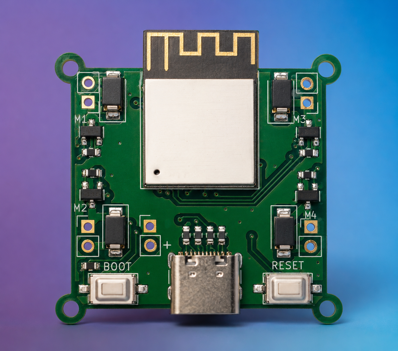
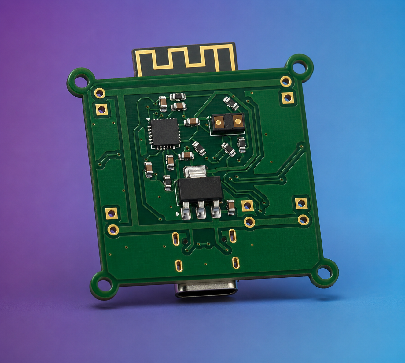
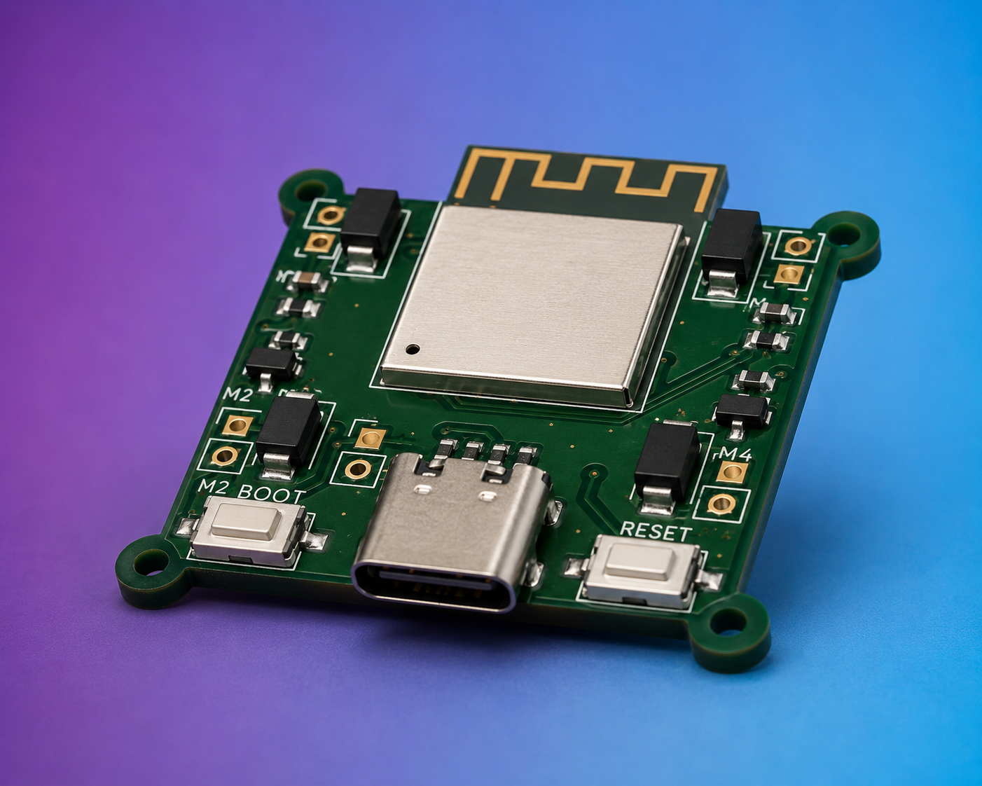
A flight controller is the onboard computer that stabilizes a quadcopter. It reads sensor data, estimates the vehicle state, and updates motor outputs fast enough to keep the aircraft balanced in real time.
On JATAYU, that flow is:
MPU6050 measures angular rate and acceleration.ESP32-S3 processes that data and runs the control loop.VL53L0X can provide short-range altitude or ground-distance data.SI2300 MOSFET stages switch the brushed DC motors using PWM.3.3 V logic power.This architecture makes JATAYU suitable for early-stage attitude control, sensor fusion, and low-altitude indoor flight experiments.
| Subsystem | Part | Role |
|---|---|---|
| Microcontroller | ESP32-S3-MINI-1 | Main processor, wireless connectivity, firmware execution |
| IMU | MPU6050 | 3-axis accelerometer and 3-axis gyroscope for motion sensing |
| Distance sensor | VL53L0X | Time-of-Flight ranging for altitude or proximity support |
| Motor stage | 4 x SI2300 N-MOSFETs | Low-side switching for four brushed motors |
| Power regulation | AP2114H-3.3 | Regulates battery input to 3.3 V for onboard electronics |
| USB interface | USB Type-C | Programming, debug access, and board power during development |
| User controls | BOOT and RESET buttons | ESP32 flashing and reset control |
| Power input | 1S Li-Po (3.7 V nominal) | Main power source |
| Path | Description |
|---|---|
JATAYU-S3.kicad_pro | KiCad project file |
JATAYU-S3.kicad_sch | Schematic source |
JATAYU-S3.kicad_pcb | PCB layout source |
GERBER FILES/ | Manufacturing Gerbers and drill files |
3D Models/ | Exported STL and GLB board models |
The ESP32-S3 acts as the main flight computer. It is responsible for sensor reads, estimator updates, motor PWM generation, and any future telemetry, tuning, or configuration interfaces.
The board includes:
MPU6050 for inertial sensingVL53L0X for distance measurementTogether, these parts support the early stages of flight stabilization, takeoff assist, and altitude-related experiments.
Each brushed motor channel is switched through an SI2300 MOSFET. This is a practical approach for small brushed quadcopters where the motors are driven directly from battery voltage and controlled through PWM.
The board is designed for a single-cell Li-Po battery. Motor current is drawn from the battery rail, while the logic domain is regulated down to 3.3 V for the ESP32-S3 and sensors.
USB Type-C, BOOT, and RESET support firmware flashing and bench development. This is especially useful during early bring-up, sensor verification, and firmware iteration.
KiCad 9.JATAYU-S3.kicad_pro.GERBER FILES/ only if you are ready to manufacture the current prototype revision.3.3 V regulation and sensor detection before testing motor outputs.JATAYU-S3.stl and JATAYU-S3.glbIf you want this repo to look complete, these are the most useful images to add:
JATAYU Flight Controller v1.2 is an ESP32-S3-based brushed quadcopter controller focused on compact hardware, onboard inertial sensing, and accessible prototype development. Its main value today is as an open flight-control hardware platform for learning, testing, and iterating toward a complete micro quadcopter stack.
| Qty | Value | Footprint | References |
|---|---|---|---|
| 9 | 10K | Resistor_SMD:R_0603_1608Metric | R4, R5, R6, R7, R9, R10, R13, R14, R15 |
| 4 | SS14 1A | Diode_SMD:D_SMA | D1, D2, D3, D4 |
| 4 | Si2300 6A | Package_TO_SOT_SMD:SOT-23 | Q1, Q2, Q3, Q4 |
| 4 | pad | Connector_PinHeader_2.54mm:PinHeader_1x02_P2.54mm_Vertical | M1, M2, M3, M4 |
| 2 | 10nF | Capacitor_SMD:C_0603_1608Metric | C1, C6 |
| 2 | 10uF | Capacitor_SMD:C_0603_1608Metric | C4, C5 |
| 2 | 22 | Resistor_SMD:R_0603_1608Metric | R1, R2 |
| 2 | 4.7K | Resistor_SMD:R_0603_1608Metric | R11, R12 |
| 2 | 5.1K | Resistor_SMD:R_0603_1608Metric | R3, R8 |
| 2 | SW_Push | Button_Switch_SMD:SW_Tactile_SPST_NO_Straight_CK_PTS636Sx25SMTRLFS | SW1, SW2 |
| 1 | 0.1uF | Capacitor_SMD:C_0603_1608Metric | C3 |
| 1 | 1uF | Capacitor_SMD:C_0603_1608Metric | C7 |
| 1 | 2.2nF | Capacitor_SMD:C_0603_1608Metric | C2 |
| 1 | AP2114H-3.3TRG1 | Package_TO_SOT_SMD:SOT-223-3_TabPin2 | U4 |
| 1 | Conn_01x02_Pin | Connector_PinHeader_2.54mm:PinHeader_1x02_P2.54mm_Vertical | Battery1 |
| 1 | ESP32-S3-MINI-1 | RF_Module:ESP32-S2-MINI-1 | U2 |
| 1 | MPU-6050 | Sensor_Motion:InvenSense_QFN-24_4x4mm_P0.5mm | U1 |
| 1 | USB_C_Receptacle_USB2.0_14P | Connector_USB:USB_C_Receptacle_GCT_USB4105-xx-A_16P_TopMnt_Horizontal | J1 |
| 1 | VL53L0CXV0DH1 | Sensor_Distance:ST_VL53L1x | U3 |

kiranj26/Posture-Tracker-Using-ESP32
Posture Correction using ESP32-MINI-1 and MU sensor (GY-521 / MPU-6050)

caggieb/ESP32-controller-WIP
Design of an ESP32 based controller with IMU, from PCB to software

KazanNinja/MM36-Data-Hub
ESP32 based DAQ board. Fit with a 4 external 16bit 5V capable ADCs, 6-DOF IMU, and GPS breakout. Has two 5V > 3.3V & 12V > 3.3V voltage dividers


shreyD2408/Custom_Esp32_Devboard
This project is a custom ESP32-S3 development board designed for robotics and embedded systems. It integrates two DRV8833 motor drivers, an MPU6050 accelerometer and gyroscope, a MAX98357A audio amplifier, and…

stoneoxmike/SelfBalancingRobot
Self Balancing Robot To this point, we have stolen EVERYTHING

It measures 35.8 × 34.2 mm and has 2 copper layers, 1.6 mm thick.
42 parts, built around the ESP32-S3-MINI-1-N8, AP2114H-3.3TRG1 and MPU-6050. The full list of its parts is on this page, with links to each part's symbol and footprint where PCBKit's library has them.
From the Quadcoach/Jatayu repository on GitHub, at the commit this page was made from: the board is JATAYU-S3.kicad_pcb and its schematic JATAYU-S3.kicad_sch. PCBKit opens the board in the browser, with nothing to install.
Its repository states no licence, so its author keeps all rights: ask Quadcoach before reusing the design.