2 layers280 × 186 mm

 qasimgulzar/atmega328-usb-interface-pcb
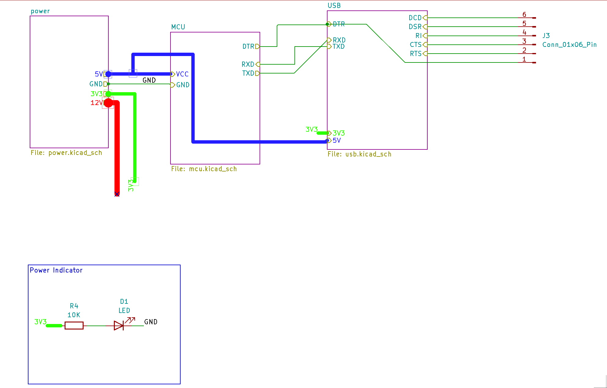
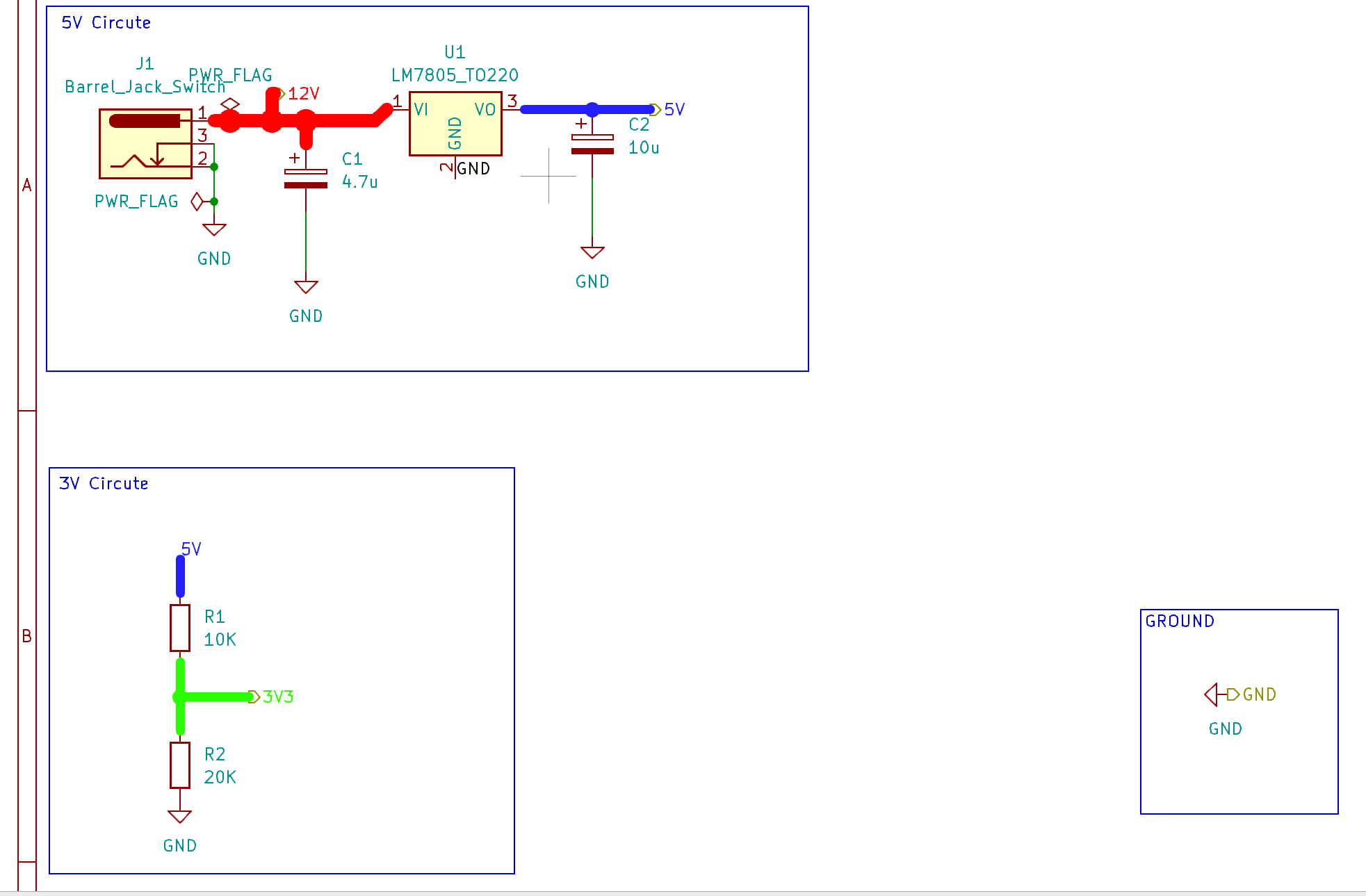
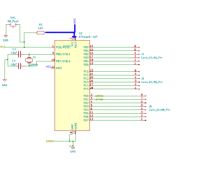
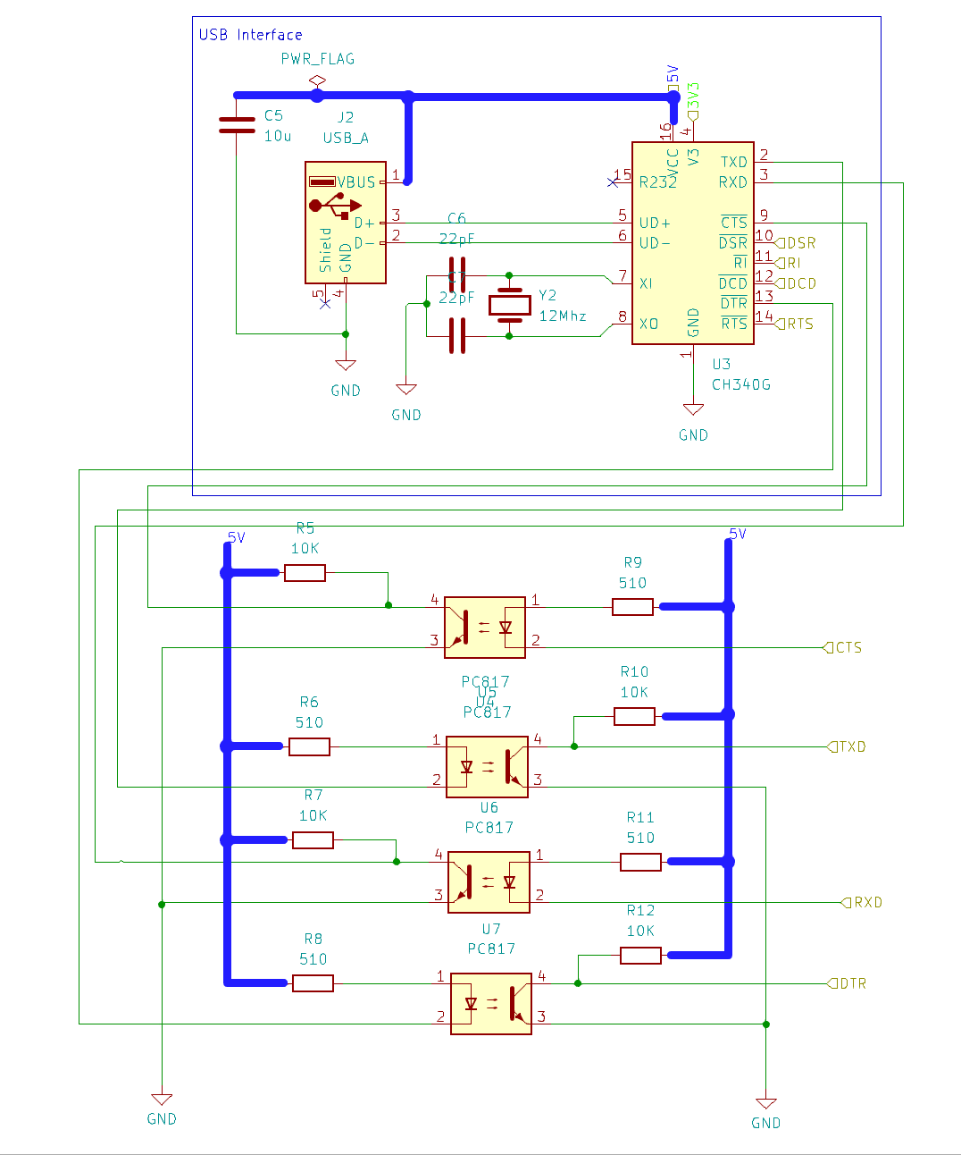
This project is a simple USB programmer for the ATMEGA328P microcontroller. It allows you to program the microcontroller using a USB connection.
Atmega328-dev board usb is an open-source printed circuit board by qasimgulzar, from the qasimgulzar/atmega328-usb-interface-pcb repository on GitHub. It is a 2-layer board of 80.2 × 80.2 mm with 26 parts on 43 nets, routed with 193 tracks and 19 vias.
It is built around the ATMEGA8-16PC and CH340G. Its parts include 7 capacitors, 6 connectors, 5 resistors, 4 ICs and 2 crystals. It belongs with the microcontroller boards boards and the AVR (ATmega, ATtiny) boards of this library.


This project is a simple USB programmer for the ATMEGA328P microcontroller. It allows you to program the microcontroller using a USB connection.
| Qty | Value | Footprint | References |
|---|---|---|---|
| 3 | Conn_01x06_Pin | Connector_PinHeader_1.27mm:PinHeader_1x06_P1.27mm_Vertical | J3, J4, J5 |
| 2 | 10K | Resistor_THT:R_Axial_DIN0207_L6.3mm_D2.5mm_P7.62mm_Horizontal | R3, R4 |
| 2 | 18pF | Capacitor_THT:C_Disc_D3.0mm_W1.6mm_P2.50mm | C3, C4 |
| 2 | 22pF | Capacitor_THT:C_Disc_D3.0mm_W1.6mm_P2.50mm | C6, C7 |
| 1 | 10u | Capacitor_THT:C_Radial_D4.0mm_H5.0mm_P1.50mm | C5 |
| 1 | 10u | Capacitor_THT:CP_Radial_D4.0mm_P1.50mm | C2 |
| 1 | 12Mhz | Crystal:Crystal_HC18-U_Vertical | Y2 |
| 1 | 16MHz | Crystal:Crystal_HC18-U_Vertical | Y1 |
| 1 | 330 | Resistor_THT:R_Axial_DIN0207_L6.3mm_D2.5mm_P7.62mm_Horizontal | R1 |
| 1 | 4.7u | Capacitor_THT:CP_Radial_D4.0mm_P1.50mm | C1 |
| 1 | 470 | Resistor_THT:R_Axial_DIN0207_L6.3mm_D2.5mm_P7.62mm_Horizontal | R2 |
| 1 | 75 | Resistor_THT:R_Axial_DIN0207_L6.3mm_D2.5mm_P7.62mm_Horizontal | R5 |
| 1 | ATmega8-16P | Socket:DIP_Socket-28_W6.9_W7.62_W10.16_W12.7_W13.5_3M_228-4817-00-0602J | U2 |
| 1 | Barrel_Jack_Switch | Connector_BarrelJack:BarrelJack_Horizontal | J1 |
| 1 | CH340G | Package_SO:SOIC-16_3.9x9.9mm_P1.27mm | U3 |
| 1 | Conn_01x08_Pin | Connector_PinHeader_1.27mm:PinHeader_1x08_P1.27mm_Vertical | J6 |
| 1 | LED | LED_THT:LED_D3.0mm | D1 |
| 1 | LM317_TO-220 | Package_TO_SOT_THT:TO-220-3_Vertical | U4 |
| 1 | LM7805_TO220 | Package_TO_SOT_THT:TO-220-3_Vertical | U1 |
| 1 | SW_Push | Button_Switch_THT:SW_TH_Tactile_Omron_B3F-10xx | SW1 |
| 1 | USB_A | Connector_USB:USB_A_Connfly_DS1095 | J2 |

ondras12345/electronic-load
Digital control for XHDZ-FZ-2g electronic load

phastmike/tmv7displaymod
This repository contains a PCB design for a solution, to the "failing LCD display problem", by OE9MKV. The implementation is based on reverse engineering some parts of the proprietary serial protocol from Kenwood.


It measures 80.2 × 80.2 mm and has 2 copper layers, 1.6 mm thick.
26 parts, built around the ATMEGA8-16PC and CH340G. The full list of its parts is on this page, with links to each part's symbol and footprint where PCBKit's library has them.
From the qasimgulzar/atmega328-usb-interface-pcb repository on GitHub, at the commit this page was made from: the board is atmega328-dev-board-usb.kicad_pcb and its schematic atmega328-dev-board-usb.kicad_sch. PCBKit opens the board in the browser, with nothing to install.
Its repository states no licence, so its author keeps all rights: ask qasimgulzar before reusing the design.