2 layers18.5 × 11.1 mm
Switch
byrantech/laptop
anyon_e, a highly integrated, high end, open source laptop. Attempt the impossible.
6 parts4.3kMIT

 pyroesp/Shiba-GD-IDE12
GD-IDE for the Toshiba GD-ROM
Shiba GD IDE is an open-source printed circuit board by pyroesp, from the pyroesp/Shiba-GD-IDE repository on GitHub. It is a 2-layer board of 85 × 70 mm with 6 parts on 33 nets, routed with 490 tracks and 59 vias.
The Sega Dreamcast uses a GD-ROM Optical Drive to read the game discs. Some clever people discovered that the optical drive uses connections similar to an IDE HDD.
If you look for Dreamcast HDD mod on Google Images you'll see some crazy stuff. People were just soldering 40 pin flat ribbon cables to the motherboard or optical drive directly, which looks pretty cool to be honest.
Some guys designed the GD-IDE which is a PCB, which is soldered on top of the optical drive of the Dreamcast, that allows you to plug in an IDE HDD.
The Shiba GD-IDE is a complete redesign of GD-IDE board for the Toshiba GD-ROM Optical Drive.
The name Shiba GD-IDE comes from the fact that the GD-ROM optical drive has a Toshiba chip on it and the name of the original board.
The original GD-IDE is designed by tawy / DragonCity.
You can find the GD-IDE on DragonCity's webpage here: Dreamcast GD-IDE
Obviously, I'm not responsible if this breaks your GD-ROM drive.
At the time of writing (21/08/2020) the boards have not yet been tested.
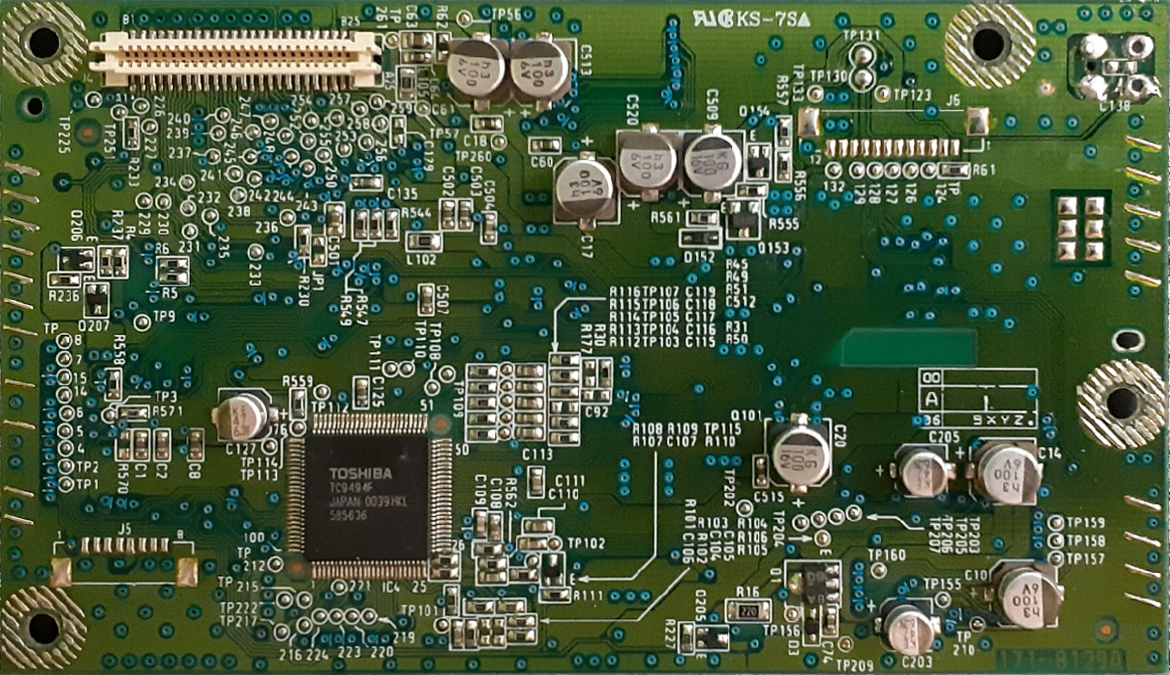
The Shiba GD-IDE is only compatible with GD-ROM drive that have a Toshiba IC on top, like shown below.
If you're going to buy some boards directly from a PCB fab, change the width of the board to 1mm.
I'm using JLCPCB to make my boards and that's why I have added 'JLCJLCJLCJLC' on to the board as a place holder for their order number.
It's kind of hidden under the 40 pin header, which is where I want it.
Just like on the GD-IDE, you want to remove pin 20 from the header pins, to make it fit with DragonCity's ribbon cable.
KiCad 3D model:
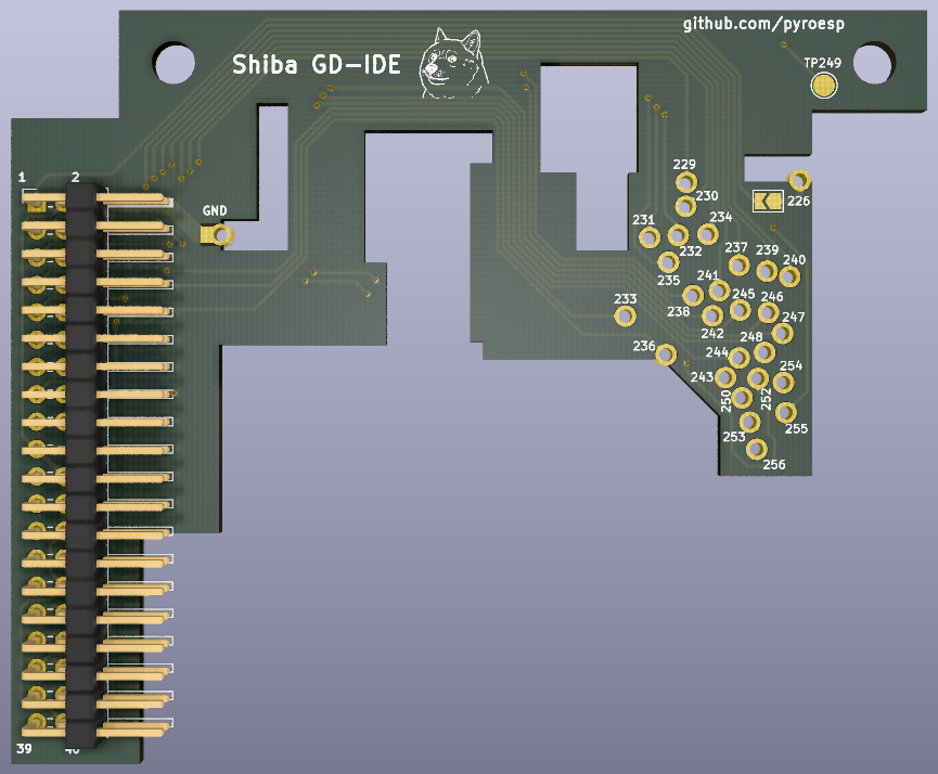
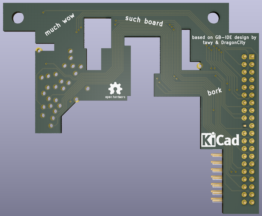
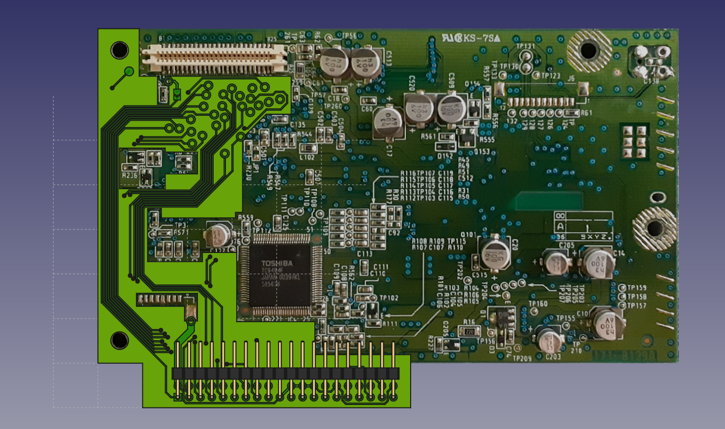
FreeCAD 3D model:
The connector is apparently a Molex 0525840579 that you can find on digikey.
I got the names of the Molex connections from the schematics found on console5.com.
The connections from the Molex connector to the IDE HDD I got from DragonCity's image below.
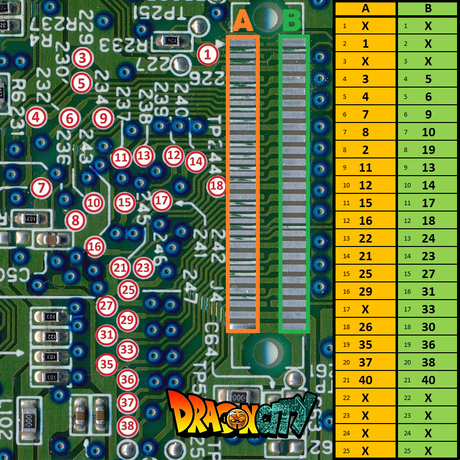
*Note: I have added the smaller numbers into the two columns to make it easier for me to map
All pinouts, pin names and connections to test points can be found in the text file in the docs folder, which looks like this:
...
IDE HDD to Dreamcast GD-ROM TP:
IDE 1 - ~RESET A2 TP226 (not needed but provide bridge, see install tutorial GD-IDE from Dragoncity.fr)
IDE 2 - GND A8/GND
IDE 3 - HD7 A4 TP229
IDE 4 - HD8 A5 TP231
IDE 5 - HD6 B4 TP230
...
CC BY 4.0
See LICENSE.md
| Qty | Value | Footprint | References |
|---|---|---|---|
| 1 | Conn_02x20_Odd_Even | Connector_PinHeader_2.54mm:PinHeader_2x20_P2.54mm_Horizontal | J1 |
| 1 | LOGO | doge:doge | G*** |
| 1 | SolderJumper-2_P1.3mm_Open_TrianglePad1.0x1.5mm | Jumper:SolderJumper-2_P1.3mm_Open_TrianglePad1.0x1.5mm | J2 |
| 1 | TestPoint_Pad_D2.0mm | TestPoint:TestPoint_Pad_D2.0mm | TP249 |
The 4 most common of 6 parts.
byrantech/laptop
anyon_e, a highly integrated, high end, open source laptop. Attempt the impossible.


Jcparkyn/dpoint
Open-source digital stylus using camera tracking and inertial measurements

VoronDesign/Voron-Hardware
Cool Hardware designed by the Voron Design group

hoglet67/RGBtoHDMI
Bare-metal Raspberry Pi project that provides pixel-perfect sampling of Retro Computer RGB/YUV video and conversion to HDMI

hackclub/OnBoard
💡 Join 1,000 teenagers and make your first PCB with a $100 grant!

Luos-io/luos_engine
Open-source and real-time orchestrator for cyber-physical-systems, to easily design, test and deploy embedded applications and digital twins.

It measures 85 × 70 mm and has 2 copper layers, 1.6 mm thick.
6 parts. The full list of its parts is on this page, with links to each part's symbol and footprint where PCBKit's library has them.
From the pyroesp/Shiba-GD-IDE repository on GitHub, at the commit this page was made from: the board is Shiba GD-IDE.kicad_pcb. PCBKit opens the board in the browser, with nothing to install.
Its repository states no licence, so its author keeps all rights: ask pyroesp before reusing the design.