
2 layers56 × 65 mm
SeaTalk1
dotnet/iot
This repo includes .NET Core implementations for various IoT boards, chips, displays and PCBs.
24 parts2.4kMIT

Arduino Pomodoro timer with LCD, buttons, RGB LED and buzzer. Includes KiCad hardware design; protoshield assembly in progress.
Timer is an open-source printed circuit board by pycoder08, from the pycoder08/arduino-pomodoro-timer repository on GitHub. It is a 2-layer board of 101.6 × 53.3 mm with 24 parts on 86 nets.
Its parts include 7 connectors, 5 resistors, 3 switches, 1 IC and 1 diode. It belongs with the lEDs and displays boards of this library.
A desktop focus timer I built around an Arduino Mega, a 16x2 LCD, three push buttons, a buzzer, and an RGB LED. It runs configurable focus/break cycles and signals each transition with color and sound.
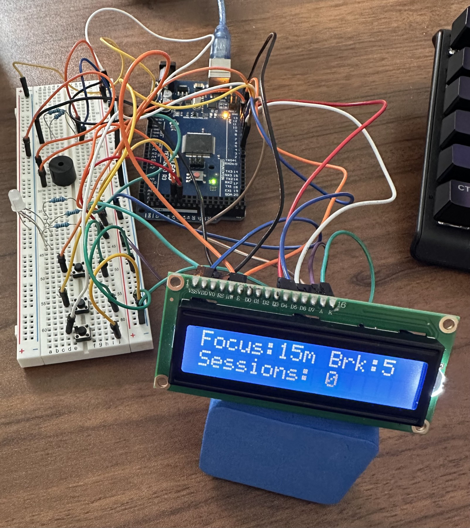
The breadboard prototype works — I've run the timer through its focus and break cycles on it. The schematic and PCB layout are drawn in KiCad and included here. I'm currently soldering the circuit onto an Arduino protoshield.
I have not fabricated the custom PCB yet, so the layout is a work in progress rather than something I'd send to a fab house today. Routing and design-rule checks still need a pass.
Button handling, the melodies, and the LED breathing are all non-blocking, so the countdown stays accurate and the buttons stay responsive no matter what else is happening.
Arduino Mega 2560, 16x2 LCD, three push buttons, a passive buzzer, a common-cathode RGB LED, resistors, breadboard, and jumper wire. LCD contrast comes from a fixed divider (roughly 8.5k to 5V and 1k to ground) rather than a trim potentiometer, so no pin is spent on it.
The sketch drives the RGB LED on pins 44–46. Those are PWM-capable on the Mega, which the breathing effect needs, and they don't exist on a Uno — remap them if you build this on a smaller board. I still need to document exact component models and resistor values.
| Function | Arduino pin |
|---|---|
| LCD RS | 12 |
| LCD enable | 11 |
| LCD D4–D7 | 5, 4, 3, 2 |
| Start / pause | 6 |
| Reset | 7 |
| Mode | 8 |
| Buzzer | 9 |
| RGB red | 44 |
| RGB blue | 45 |
| RGB green | 46 |
Buttons are wired active-low using INPUT_PULLUP and are debounced in software. This table covers
the software pin assignment only — check LCD contrast wiring, your RGB LED's common pin, and
current-limiting resistors against your own build.
timer.ino in the Arduino IDE, letting it create the enclosing timer folder if prompted.LiquidCrystal library is installed. EEPROM ships with the IDE.Timer.kicad_pro is the main project, with Timer.kicad_sch for the schematic and Timer.kicad_pcb for the layout. Arduino_MountingHole.pretty holds the custom mounting-hole footprints the board references.
focus_timer_schematic.kicad_sch is an earlier sheet covering just the Arduino header connections, kept for reference.
I wrote this project's firmware with AI assistance. The circuit design, breadboard build and testing, schematic capture, PCB layout, and protoshield assembly are my own work.
| Qty | Value | Footprint | References |
|---|---|---|---|
| 6 | MountingHole_3.2mm | Arduino_MountingHole:MountingHole_3.2mm | MH1, MH2, MH3, MH4, MH5, MH6 |
| 3 | 220 | Resistor_THT:R_Axial_DIN0207_L6.3mm_D2.5mm_P10.16mm_Horizontal | R1, R2, R3 |
| 3 | SW_Push | Button_Switch_THT:SW_PUSH_6mm | SW1, SW2, SW3 |
| 2 | Analog | Connector_PinSocket_2.54mm:PinSocket_1x08_P2.54mm_Vertical | J3, J5 |
| 1 | 10k | Resistor_THT:R_Axial_DIN0207_L6.3mm_D2.5mm_P10.16mm_Horizontal | R4 |
| 1 | 1k | Resistor_THT:R_Axial_DIN0207_L6.3mm_D2.5mm_P10.16mm_Horizontal | R5 |
| 1 | Buzzer | Buzzer_Beeper:MagneticBuzzer_ProSignal_ABT-410-RC | BZ1 |
| 1 | Communication | Connector_PinSocket_2.54mm:PinSocket_1x08_P2.54mm_Vertical | J6 |
| 1 | Digital | Connector_PinSocket_2.54mm:PinSocket_2x18_P2.54mm_Vertical | J7 |
| 1 | LED_RGB | LED_SMD:LED_RGB_5050-6 | D1 |
| 1 | PWM | Connector_PinSocket_2.54mm:PinSocket_1x08_P2.54mm_Vertical | J4 |
| 1 | PWM | Connector_PinSocket_2.54mm:PinSocket_1x10_P2.54mm_Vertical | J2 |
| 1 | Power | Connector_PinSocket_2.54mm:PinSocket_1x08_P2.54mm_Vertical | J1 |
| 1 | RC1602A | Display:RC1602A | U1 |
It measures 101.6 × 53.3 mm and has 2 copper layers, 1.6 mm thick.
24 parts. The full list of its parts is on this page, with links to each part's symbol and footprint where PCBKit's library has them.
From the pycoder08/arduino-pomodoro-timer repository on GitHub, at the commit this page was made from: the board is Timer.kicad_pcb and its schematic Timer.kicad_sch. PCBKit opens the board in the browser, with nothing to install.
Its repository states no licence, so its author keeps all rights: ask pycoder08 before reusing the design.
dotnet/iot
This repo includes .NET Core implementations for various IoT boards, chips, displays and PCBs.

pascallanger/DIY-Multiprotocol-TX-Module
Multiprotocol TX Module (or MULTI-Module) is a 2.4GHz transmitter module which controls many different receivers and models.


rusefi/rusefi
rusefi - GPL internal combustion engine control unit

DraftShift/StealthChanger
Tool changing system for Vorons and other front mount printer motion systems, not just stealthburner.

VoronDesign/Voron-Hardware
Cool Hardware designed by the Voron Design group

hackclub/OnBoard
💡 Join 1,000 teenagers and make your first PCB with a $100 grant!
