2 layers45.7 × 20.3 mm

 psychogenic/gamepad-pmod7
CH32V003-based 2xSNES controller interface PMOD
Gamepad pmod is an open-source printed circuit board by psychogenic, from the psychogenic/gamepad-pmod repository on GitHub, published under the GPL-3.0 licence. It is a 2-layer board of 29.3 × 73 mm with 93 parts on 22 nets, routed with 256 tracks and 47 vias.
It is built around the CH32V003F4U6, CL21A106KOQNNNE and 10129382-912001BLF, with the APT1608SURCK and RC0402FR-0710KL among its other parts. Its parts include 8 capacitors, 5 connectors, 3 resistors, 1 IC and 1 diode. It belongs with the keyboards and input boards and the RISC-V boards of this library.


CH32V003-based 2xSNES-compatible controller interface PMOD
Copyright (C) 2025 Pat Deegan, psychogenic.com
Released as free and open source software under the terms of the GPL (see LICENSE)
This simple module allows 1 or 2 SNES controllers to report their state over 3 pins, and is used with my SNES PMOD. Here's the first prototype:
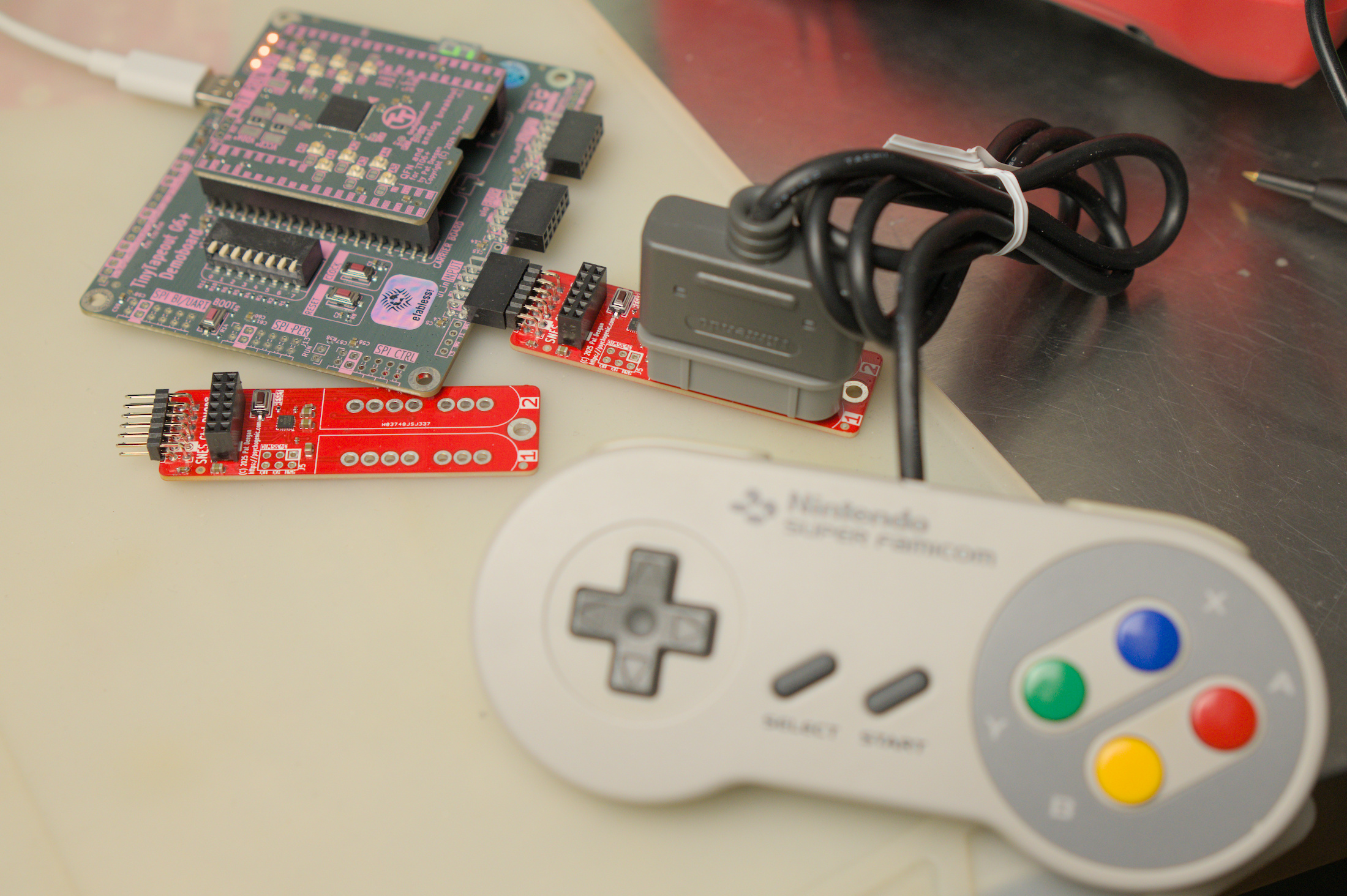
It is a variation on the SNES controller protocol that automatically polls the controllers and reports back values. The main differences are that the data may be sampled on the rising edge of the clock and the latch happens at the end so it acts like a SIPO (serial in, parallel out) shift register and you can just save the values whenever you see the pulse.
This allows for using the controllers as read-only devices (i.e. using only input pins on your side) and will send all values in a single transaction (e.g. 24 bits of data in one burst for two controllers).
It may be easily configured (by editing the config definitions file) to specify:
whether to report continuously, only on change and/or with a maximum interval between reports (e.g. only on change but at least every 2 seconds, as is the default configuration);
the number of controllers (1 or 2);
the PMOD pins to report back on;
the bitrate at which these reports are sent;
A verilog module is provided that makes inclusion in projects simple. Include the gamepad_pmod.v source file in your build and, somewhere in your project, instantiate one of
* gamepad_pmod_dual -- to support two controllers, or

* gamepad_pmod_single -- to only support a single controller
You then feed the gamepad module the input data, clock and latch from the outside world and from there you receive information about which buttons are pressed at any time.
More information and basic samples are in the verilog directory.
A nice example of an implementation using this module is Uri's 2048 game.
Though it is designed for use with FPGA/ASIC projects, the reports from controller(s) may also be read on an RP2040 (e.g. the Tiny Tapeout demoboard) using code like the sample in gamepad_reader.py.
This code all runs on a simple PMOD that's little more than a CH32V003 and headers to connect to the controllers and PMOD.
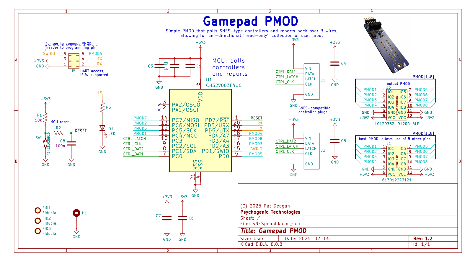
The CH32V polls the controllers as per the standard method for these controllers and, on change or timeout, shoots data out through the peripheral PMOD header, as described in "protocol" below.
It also includes:
a PMOD host header, so you could in theory leverage the 5 unused input pins using another PMOD
an extra 2x3 100 mil header that allows you to jumper the PMOD IO4 into the SWDIO pin, to allow for programming through the PMOD header.
The complete project is available under hardware/GamepadPMOD.
Reports are sent in the following manner, by default over 3 pins:
latch;
clock; and
data
Sample waveform, one controller disconnected, the other holding 3 buttons:
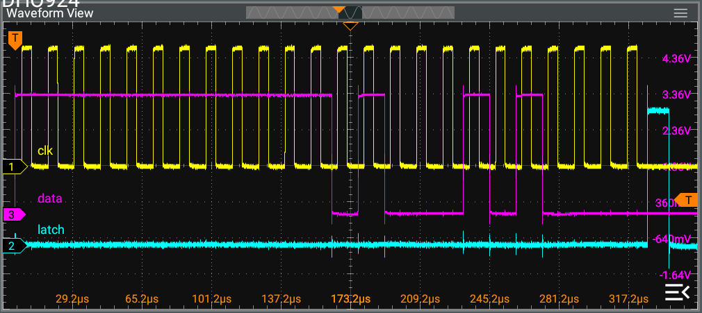
A disconnected controller reports all 1s, which includes impossible combinations (e.g. up and down at the same time), and lets us detect controller presence.
Data will be asserted on the data line prior to the clock going high and remain valid past when the clock goes low. After all bits are sent, latch pulses high.
Each bit will be sent in turn, for each controller, in the following order:
B
Y
select
start
up
down
left
right
A
X
L
R
With a HIGH value indicating the relevant button is pressed.
The default setup we'll use for Tiny Tapeout is:
100kHz clock rate, so that even slowish projects can leverage the input;
Latch on PMOD IO5 (ui_in[4] on the demoboards, PMODs aren't 0-indexed);
Clock on PMOD IO6 (ui_in[5]);
Data on PMOD IO7 (ui_in[6]);
2 controllers, i.e. 24 bits of data before the latch pulses; and
report-on-change but with a maximum interval between bursts of 1 second (minimum interval is about 1.66ms, or a 600Hz rate for reports, like the SNES console)
Though the SNES consoles only polled at 60Hz, nicely sync'ed to the framerate, if you're a speedrunner you could hit some issues if we do the same, as the PMOD isn't synchronized with the system clock.
After discussion with the community and tests with both el-cheapo chinese controllers and an old famicom thing from the 90s, I'm 10x-ing the controller polling rate to 600Hz. This doesn't actually impact the rate at which the controllers are clocked, it's just that it happens more often and doesn't seem to cause issue.
From the actual SNES controller perspective, the interaction looks like this:
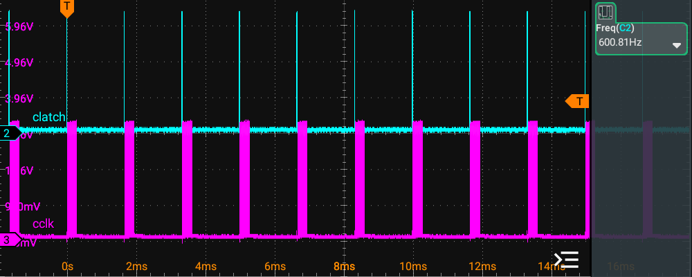
You can see that, on that side, the latch signal comes before the burst of clocking and it's being polled at just around 600Hz.
Since the clocks in projects are independent from the moment at which reports can arrive, its best to do some cleaning for clock domain crossing to ensure stability.
Best and easiest thing is just to use the gaming_pmod sample module, which handles this.
If you're looking to roll your own, in verilog this would look like classic synchronizer patterns, e.g.
reg [1:0] pmod_data_sync;
always @(posedge clk) begin
  if (~rst_n) begin
    pmod_data_sync  <= 2'b0;
  end else begin
    pmod_data_sync  <= {pmod_data_sync[0], pmod_data};
  end
end
Whereas with Amaranth, it's little more than using the FFSynchronizer
FFSynchronizer(i=pmod_data, o=pmod_data_sync)A selection of pre-compiled firmware is available in firmware, but you may want to build yourself...
To do so, you'll need the awesome ch32v003fun SDK, by cnlohr, which is already included here as a submodule. To ensure you have that, you can do
git submodule update --init --recursivefrom the top level directory.
Then simply (optionally) hook-up a supported programmed to the target module and
cd src
make
That should be it.
The CH32V firmware may be updated using a suitable programmer. However, to assist the production run and to make future updates easy I updated the pico_ch32v003_prog to use less memory and burn firmware.
The fork and a sample using it is available on gamepad-update.
Adding a jumper between the two top pins on the 6-pin header, between PRJ and SWIO:
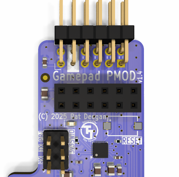
will connect PMOD IO4 to the programming pin and allow the RP2040 on the demoboard to write new firmware.
These controller connectors aren't actually meant to be used this way. In order to provide a bit of stability, we 3D print little feet:
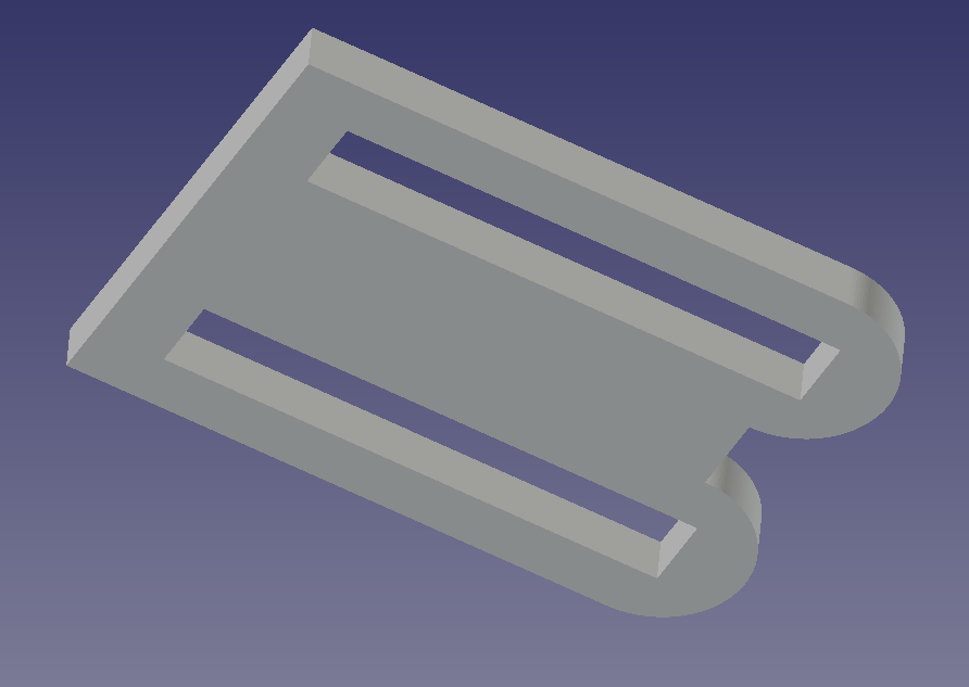
The STL file for this is hardware/gamepad-footstabv1p0-tol2.stl
| Qty | Value | Footprint | References |
|---|---|---|---|
| 64 | StitchingVia-0.4mmDrill | flyingcarsfootprints:StitchingVia-0.4mmDrill | STITCH10, STITCH10, STITCH10, STITCH10, STITCH10, STITCH10, STITCH10, STITCH10, STITCH10, STITCH10, STITCH10, STITCH10, STITCH11, STITCH11, STITCH12, STITCH12 +48 |
| 4 | C_10u_0805_35V | Capacitor_SMD:C_0805_2012Metric | C1, C4, C5, C6 |
| 3 | Fiducial | Fiducial:Fiducial_1mm_Mask2mm | FID1, FID2, FID3 |
| 2 | C_100n_0402_50V | Capacitor_SMD:C_0402_1005Metric | C3, C8 |
| 2 | C_1u_0603_50V | Capacitor_SMD:C_0603_1608Metric | C2, C7 |
| 2 | SFC connector VERT | psychogenic:snes_connector | J1, J2 |
| 1 | 10129382-912001BLF | TinyTapeout:PinHeader_2x06_P2.54mm_PMODPeriph2B | J3 |
| 1 | 200R | Resistor_SMD:R_0402_1005Metric | R3 |
| 1 | 434121025816 | TinyTapeout:434121025816 | SW1 |
| 1 | 613012243121 | TinyTapeout:PinSocket_2x06_P2.54mm_PMODHost1A | J4 |
| 1 | CH32V003F4U6 | Package_DFN_QFN:QFN-20-1EP_3x3mm_P0.4mm_EP1.65x1.65mm | U1 |
| 1 | Conn_02x03_Odd_Even | Connector_PinHeader_2.54mm:PinHeader_2x03_P2.54mm_Vertical | J5 |
| 1 | LED | LED_SMD:LED_0603_1608Metric | D1 |
| 1 | MountingHole_Pad | MountingHole:MountingHole_3.2mm_M3_ISO7380_Pad | H1 |
| 1 | PMOD_LOGO | TinyTapeout_PMOD:TT_PMOD_Logo_7mm | LOGO1 |
| 1 | PSYLOGO | flyingcarsfootprints:PsychoLogoSmall | {$REFERENCE} |
| 1 | PsychoLogoMini | flyingcarsfootprints:PsychologoMini | G*** |
| 1 | R_10k_0402 | Resistor_SMD:R_0402_1005Metric | R1 |
| 1 | R_1k_0402 | Resistor_SMD:R_0402_1005Metric | R2 |
| 1 | StitchingVia-0.3mm | flyingcarsfootprints:StitchingVia-0.3mm | STITCH1 |
| 1 | TT_PMOD_Logo_5mm | TinyTapeout_PMOD:TT_PMOD_Logo_5mm | TTPMODLOGO |
The 92 most common of 93 parts.


alex1324575/snake-pcb-business-card
STM32-powered PCB business card with a 10x9 LED Snake game, USB-C power, and passive NFC. KiCad hardware, C firmware, and verification reports.

DeadlySIn777/Controller
Unfinished CNC controller motherboard: native KiCad sources, rules, DSN and global routing review

MukeshSethy/micromouse-runner
This is my repo for the first version of full size micromouse development.

ricknoboa137/BioZ-muscle-monitor
A portable, battery-powered bioimpedance spectroscopy (BIS) device that measures biceps muscle impedance during and after exercise, to track fatigue and fluid shift.

danbrunski/canary
Four 25 F cells in series for CANary-PWR's LTC3350 hold-up, on a lead (design record: docs/CANary-PWR-Spec.md §P4). The board has no active parts: four cells, an NTC, two Kelvin net ties and a Micro-Fit 2 × 5 header.
It measures 29.3 × 73 mm and has 2 copper layers, 1.6 mm thick.
93 parts, built around the CH32V003F4U6, CL21A106KOQNNNE, 10129382-912001BLF and APT1608SURCK. The full list of its parts is on this page, with links to each part's symbol and footprint where PCBKit's library has them.
From the psychogenic/gamepad-pmod repository on GitHub, at the commit this page was made from: the board is hardware/GamepadPMOD/GamepadPMOD.kicad_pcb and its schematic hardware/GamepadPMOD/GamepadPMOD.kicad_sch. PCBKit opens the board in the browser, with nothing to install.
Its repository publishes it under the GPL-3.0 licence: you may reuse it on that licence's terms (keep the author's notice, and for a copyleft licence share your changes alike).