
2 layers19 × 76 mm
Sub
google/mozc-devices
Circuit diagrams and firmware source code for Gboard DIY keyboards
15 parts3kApache-2.0
 PrototypeZone/tech150
Welcome to TECH 150 - Please attend your labs with your parts kit and your lab manual. Bookstore will possibly be restocked 2025-05-23.
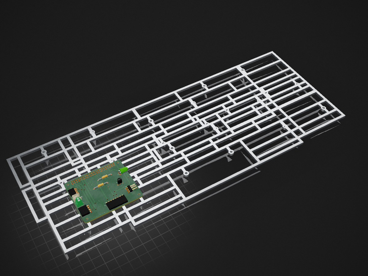
Crossover2025-12-29 is an open-source printed circuit board by PrototypeZone, from the PrototypeZone/tech150 repository on GitHub, published under the AGPL-3.0 licence. It is a 2-layer board of 65 × 56 mm with 15 parts on 44 nets, routed with 140 tracks and 15 vias.
Its parts include 7 connectors, 2 resistors, 1 diode and 1 transistor.
Welcome to TECH 150 - Please attend your labs with your parts kit and your lab manual. Bookstore will possibly be restocked 2025-05-23.
2025 May-June Lab Schedule (Tentative)
| Week | A | B | Topics/Assignment | Due % |
|---|---|---|---|---|
| 1 | 2025-05-07 | 2025-05-08 | Exp. 1 Part 1, Part 2: Introduction to Semiconductors xy mode | Show lab01 measurements |
| 2 | 2025-05-14 | 2025-05-15 | Exp. 2 (rectification and clipping during lab) Part 1, Part 2, Part 3: Diodes and Applications We have MultiSim on myApps | Lab01 paper copy, Show lab02 measurements |
| 2025-05-19 | 2025-05-19 | Monday Public Holiday (Victoria Day) - College Closed | ||
| 3 | 2025-05-21 | 2025-05-22 | Exp. 3 Part 1: Special Purpose Diodes Steps 1-9 Conclusion/Questions: Part 1: 1,2,3 | Lab02 paper copy, Show lab03 Table 3-2 |
| 4 | 2025-05-29 | Exp. 8 Part 1 Steps 1-10 step 11 IDSS (IDS with VGS shorted), Part 3: Field-Effect Transistors (FETs) (Part 1 Step 2 should read Keep VGG at 0V and slowly increase VDD (to about 1.4V) until VDS is 1.0V and Part3 Rs use 220Ohm, Rd use 3.3kOhm) | Lab03 paper copy, Show lab04 measurements | |
| 2025-06-04 | Exp. 8 Part 1 Steps 1-10 step 11 IDSS (IDS with VGS shorted), Part 3: Field-Effect Transistors (FETs) (Part 1 Step 2 should read Keep VGG at 0V and slowly increase VDD (to about 1.4V) until VDS is 1.0V and Part3 Rs use 220Ohm, Rd use 3.3kOhm) | Lab03 paper copy, Show lab04 measurements | ||
| 5 | 2025-06-05 | Exp. 9 Part 1 (Step 4 use Rs=560 Ohm instead of 620 Ohm), Part 2: FET Amplifiers and Switching Circuits | Lab04 paper copy, Show lab05 measurements | |
| Reminder that parts signed out from the parts crib are to be returned the same day | ||||
| 6 | 2025-06-11 | Exp. 9 Part 1 (Step 4 use Rs=560 Ohm instead of 620 Ohm) | Submit Exp. 8 Part 1 and Part 3 paper copy | |
| Show the completed Table 9-2 prior to leaving the lab. | ||||
| For next week: | ||||
| -Each student is to build Figure 9-2 (without the JFET before the lab) | ||||
| -Regarding submitting part 1, please make sure that you are submitting on paper you have rights to | ||||
| 2025-06-12 | Exp. 9 Part 3: FET Amplifiers (Use R2=560Ohm, R3=200kOhm, R4=470kOhm) | Lab05 paper copy, Show lab06 measurements | ||
| -Regarding recording measurements for part 3, please make sure that you are writing/submitting Tables 9-6,9-7,9-8,9-9, Step 6 What effect if any? Q1 and Q2 on paper you have rights to | ||||
| 7 | 2025-06-18 | Individual Lab Overall Evaluation Figure 9-2 built without the JFET prior to the lab (5%) | Exp.9 Part 1 paper copy, labtest1 | |
| 2025-06-19 | Individual Lab Overall Evaluation Figure 9-2 built without the JFET prior to the lab (5%) | Exp.9 Part 3 paper copy, labtest1 | ||
| 2025-06-25 | 2025-06-26 | Reading Week, No Class Scheduled |
| Qty | Value | Footprint | References |
|---|---|---|---|
| 4 | MountingHole_2.7mm_M2.5 | MountingHole:MountingHole_2.7mm_M2.5 | MH1, MH2, MH3, MH4 |
| 1 | 2.2k | Resistor_THT:R_Axial_DIN0207_L6.3mm_D2.5mm_P15.24mm_Horizontal | R1 |
| 1 | 220 | Resistor_THT:R_Axial_DIN0207_L6.3mm_D2.5mm_P15.24mm_Horizontal | R2 |
| 1 | 2N4124 | Package_TO_SOT_THT:TO-92_Inline_Wide | Q1 |
| 1 | Conn_01x02_Pin | Connector_JST:JST_PH_S2B-PH-K_1x02_P2.00mm_Horizontal | J6 |
| 1 | Conn_01x03_Pin | Connector_PinHeader_2.54mm:PinHeader_1x03_P2.54mm_Horizontal | J4 |
| 1 | Conn_01x04_Female | Connector_PinSocket_2.54mm:PinSocket_1x04_P2.54mm_Horizontal | J3 |
| 1 | Conn_01x08_Socket | Connector_PinSocket_2.54mm:PinSocket_1x08_P2.54mm_Horizontal | J5 |
| 1 | GPIO | Connector_PinSocket_2.54mm:PinSocket_2x20_P2.54mm_Vertical | J1 |
| 1 | LED | LED_THT:LED_D5.0mm_Horizontal_O1.27mm_Z3.0mm | D1 |
| 1 | Qwiic Right Angle | Connector_PinSocket_2.00mm:PinSocket_1x04_P2.00mm_Horizontal | J2 |
| 1 | Screw_Terminal_01x02 | TerminalBlock_Phoenix:TerminalBlock_Phoenix_MPT-0,5-2-2.54_1x02_P2.54mm_Horizontal | J7 |
It measures 65 × 56 mm and has 2 copper layers, 1.6 mm thick.
15 parts. The full list of its parts is on this page, with links to each part's symbol and footprint where PCBKit's library has them.
From the PrototypeZone/tech150 repository on GitHub, at the commit this page was made from: the board is media/Crossover2025-12-29.kicad_pcb and its schematic media/Crossover2025-12-29.kicad_sch. PCBKit opens the board in the browser, with nothing to install.
Its repository publishes it under the AGPL-3.0 licence: you may reuse it on that licence's terms (keep the author's notice, and for a copyleft licence share your changes alike).
google/mozc-devices
Circuit diagrams and firmware source code for Gboard DIY keyboards

hoglet67/RGBtoHDMI
Bare-metal Raspberry Pi project that provides pixel-perfect sampling of Retro Computer RGB/YUV video and conversion to HDMI

mntmn/amiga2000-gfxcard
MNT VA2000, an Open Source Amiga 2/3/4000 Graphics Card (Zorro II/III), written in Verilog

hackclub/OnBoard
💡 Join 1,000 teenagers and make your first PCB with a $100 grant!

kenp-io/not-for-airpods-repairs
The content of this repository is licensed under the WTFPL License. Please have a close look at the terms before using this material.

Luos-io/luos_engine
Open-source and real-time orchestrator for cyber-physical-systems, to easily design, test and deploy embedded applications and digital twins.

Chrismettal/EleLab_v2
Cheap DIY lab system for hobbyists and the tinkering folk
