2 layers121.9 × 119.2 mm
VARIATEUR 0 10V
AssaadMH/power-electronics-simulation
AC power controllers, a 0–10 V industrial dimmer, a digital tachometer and a brushless drive, designed and simulated end to end.
39 parts1MIT
 profdc9/TriacControl2
Triac Phase Controlled by analog / PWM signal
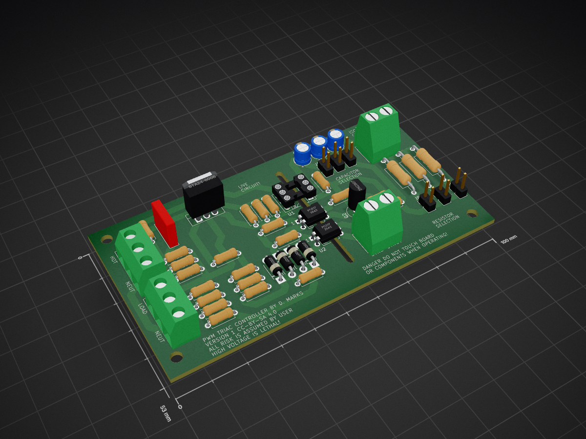
TriacControl is an open-source printed circuit board by profdc9, from the profdc9/TriacControl repository on GitHub. It is a 2-layer board of 100 × 53 mm with 53 parts on 37 nets, routed with 216 tracks and 0 vias.
It is built around the BTA24-600B and MOC3023. Its parts include 25 resistors, 4 capacitors, 4 diodes, 4 connectors and 3 ICs.


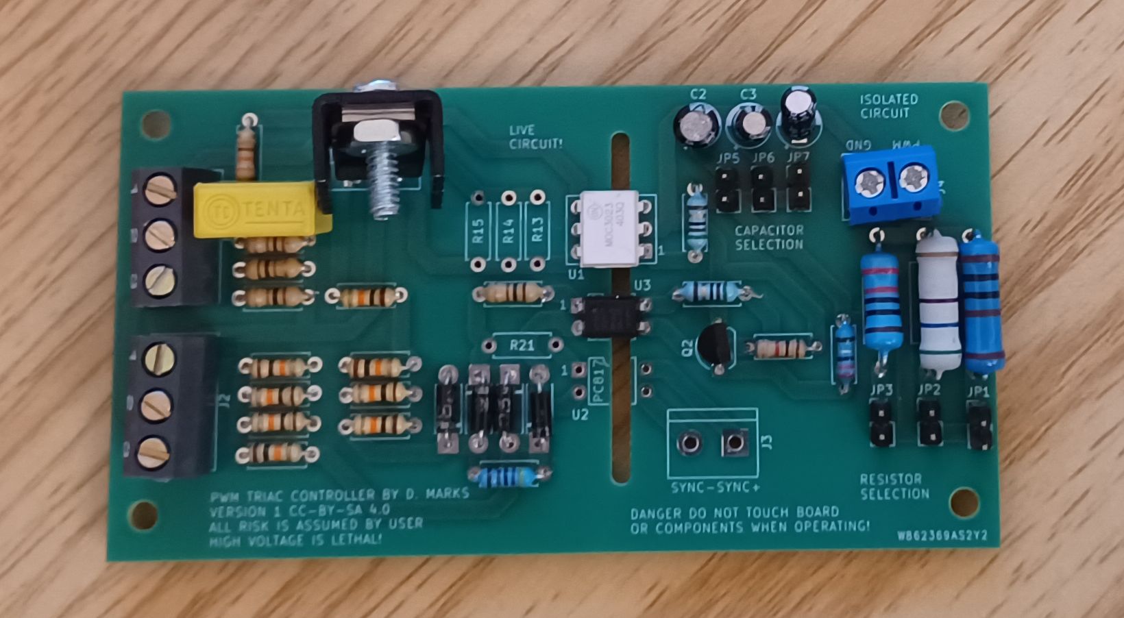
This is an optoisolated triac motor speed controller where the phase control of the motor AC signal may be controlled by an analog or PWM signal. Typically, a universal motor tool such as a drill or a router could have it's speed varied this way. A PWM signal would usually be supplied by a microcontroller. This motor speed control is open-loop and you have to add a tachometer if you want to be able to vary the motor speed to achieve a particular rotation rate.
The voltage for the control may be 3.3 v, 5v, or up to 24 v. A resistor (one of R17,R18,R19) and a capacitor (one of C2,C3,C4) determine how the voltage/PWM signal varies the motor speed control. The minimum control voltage to turn on the triac is about 1.75 V. 3.3V control uses a 100 ohm resistor and a 22 uF capacitor, a 5 V control uses a 470 ohm resistor and a 47 uF capacitor, 12 volts uses a 2k2 resistor and 47 uF capacitor, and 24 V uses a 4k7 resistor an 47 uF capacitor. You may have to experiment to get it to put the control voltage into the required range. If you have an incandescent light bulb, you can use that as the load rather than the motor to see how bright it gets as you vary the control voltage. Three resistors and three capacitors may be placed on the board and selected using jumpers so that soldering need not be performed to try different values.
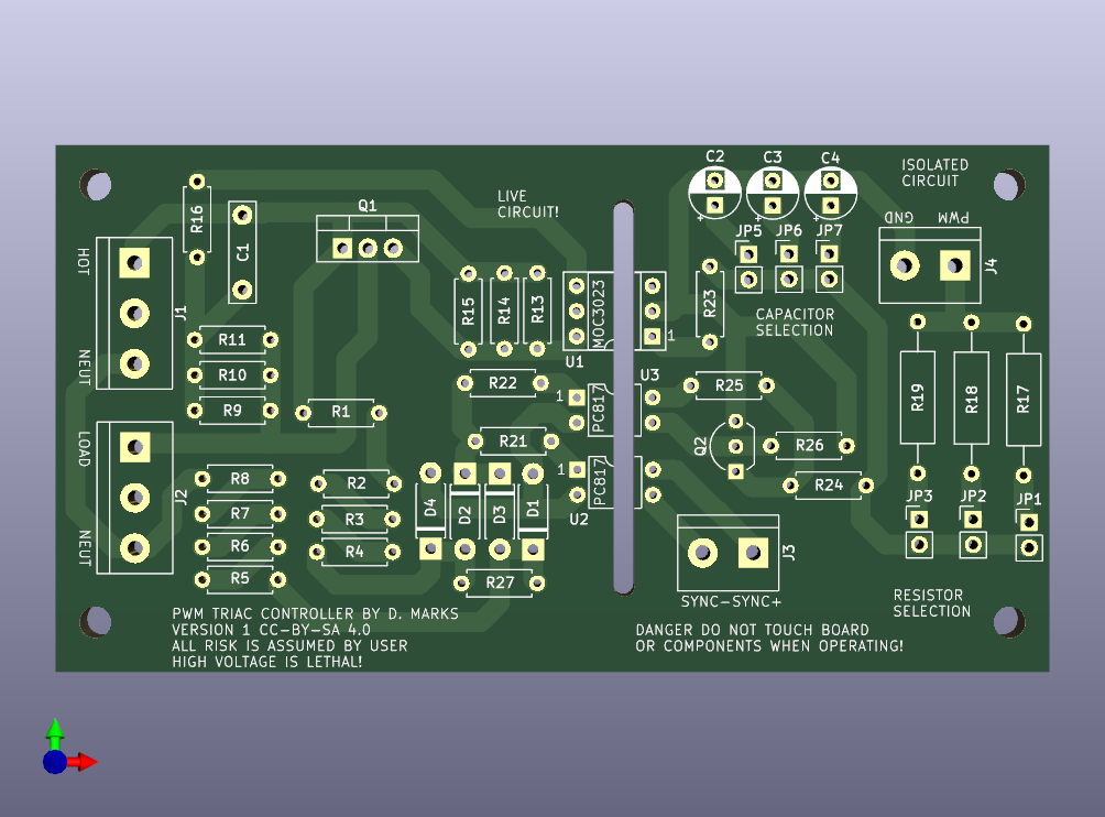
| Qty | Value | Footprint | References |
|---|---|---|---|
| 8 | 10k | Resistor_THT:R_Axial_DIN0207_L6.3mm_D2.5mm_P7.62mm_Horizontal | R1, R2, R3, R4, R5, R6, R7, R8 |
| 6 | Pinhead | Connector_PinHeader_2.54mm:PinHeader_1x02_P2.54mm_Vertical | JP1, JP2, JP3, JP5, JP6, JP7 |
| 4 | 100R | Resistor_THT:R_Axial_DIN0207_L6.3mm_D2.5mm_P7.62mm_Horizontal | R9, R10, R21, R22 |
| 4 | 1N4007 | Diode_THT:D_DO-41_SOD81_P7.62mm_Horizontal | D1, D2, D3, D4 |
| 4 | MountingHole | MountingHole:MountingHole_3.2mm_M3 | H1, H2, H3, H4 |
| 3 | 220k | Resistor_THT:R_Axial_DIN0207_L6.3mm_D2.5mm_P7.62mm_Horizontal | R13, R14, R15 |
| 2 | 3k3 | Resistor_THT:R_Axial_DIN0309_L9.0mm_D3.2mm_P15.24mm_Horizontal | R17, R18 |
| 2 | 47R | Resistor_THT:R_Axial_DIN0207_L6.3mm_D2.5mm_P7.62mm_Horizontal | R23, R25 |
| 2 | PC817 | Package_DIP:DIP-4_W7.62mm | U2, U3 |
| 1 | 10 uF | Capacitor_THT:CP_Radial_D5.0mm_P2.50mm | C4 |
| 1 | 100 nF, 400 V | Capacitor_THT:C_Rect_L10.0mm_W2.5mm_P7.50mm_MKS4 | C1 |
| 1 | 1k | Resistor_THT:R_Axial_DIN0207_L6.3mm_D2.5mm_P7.62mm_Horizontal | R26 |
| 1 | 22 uF | Capacitor_THT:CP_Radial_D5.0mm_P2.50mm | C3 |
| 1 | 2N2907 | Package_TO_SOT_THT:TO-92_Inline_Wide | Q2 |
| 1 | 330R | Resistor_THT:R_Axial_DIN0207_L6.3mm_D2.5mm_P7.62mm_Horizontal | R16 |
| 1 | 47 uF | Capacitor_THT:CP_Radial_D5.0mm_P2.50mm | C2 |
| 1 | 4R7 | Resistor_THT:R_Axial_DIN0207_L6.3mm_D2.5mm_P7.62mm_Horizontal | R24 |
| 1 | 4k7 | Resistor_THT:R_Axial_DIN0207_L6.3mm_D2.5mm_P7.62mm_Horizontal | R27 |
| 1 | 820R | Resistor_THT:R_Axial_DIN0309_L9.0mm_D3.2mm_P15.24mm_Horizontal | R19 |
| 1 | AC LINE | TerminalBlock:TerminalBlock_bornier-3_P5.08mm | J1 |
| 1 | BTA24-600B | Package_TO_SOT_THT:TO-220-3_Vertical | Q1 |
| 1 | LOAD | TerminalBlock:TerminalBlock_bornier-3_P5.08mm | J2 |
| 1 | MOC3023 | Package_DIP:DIP-6_W7.62mm_Socket | U1 |
| 1 | MountingHole | MountingHole:MountingHole_2.1mm | H5 |
| 1 | NC | Resistor_THT:R_Axial_DIN0207_L6.3mm_D2.5mm_P7.62mm_Horizontal | R11 |
| 1 | PWM | TerminalBlock:TerminalBlock_bornier-2_P5.08mm | J4 |
| 1 | ZEROCROSS | TerminalBlock:TerminalBlock_bornier-2_P5.08mm | J3 |
It measures 100 × 53 mm and has 2 copper layers, 1.6 mm thick.
53 parts, built around the BTA24-600B and MOC3023. The full list of its parts is on this page, with links to each part's symbol and footprint where PCBKit's library has them.
From the profdc9/TriacControl repository on GitHub, at the commit this page was made from: the board is TriacControl.kicad_pcb and its schematic TriacControl.kicad_sch. PCBKit opens the board in the browser, with nothing to install.
Its repository states no licence, so its author keeps all rights: ask profdc9 before reusing the design.
AssaadMH/power-electronics-simulation
AC power controllers, a 0–10 V industrial dimmer, a digital tachometer and a brushless drive, designed and simulated end to end.


davidphilipbarr/Sweep
Sweep - a small promicro based keyboard inspired by the Ferris.

hoglet67/RGBtoHDMI
Bare-metal Raspberry Pi project that provides pixel-perfect sampling of Retro Computer RGB/YUV video and conversion to HDMI


polpo/picogus
Emulation of ISA sound cards and CD-ROM on Raspberry Pi Pico (GUS, SB/Adlib, MPU-401, Tandy, CMS, Panasonic CD-ROM) with USB mouse/joystick support

strangeparts/niubi-headphones
Flexible circuit board design for adding a headphone jack to an iPhone 7