2 layers116.8 × 30 mm
Type d
google/mozc-devices
Circuit diagrams and firmware source code for Gboard DIY keyboards
14 parts3kApache-2.0

 proboterror/SCART_Cable_Breakout2
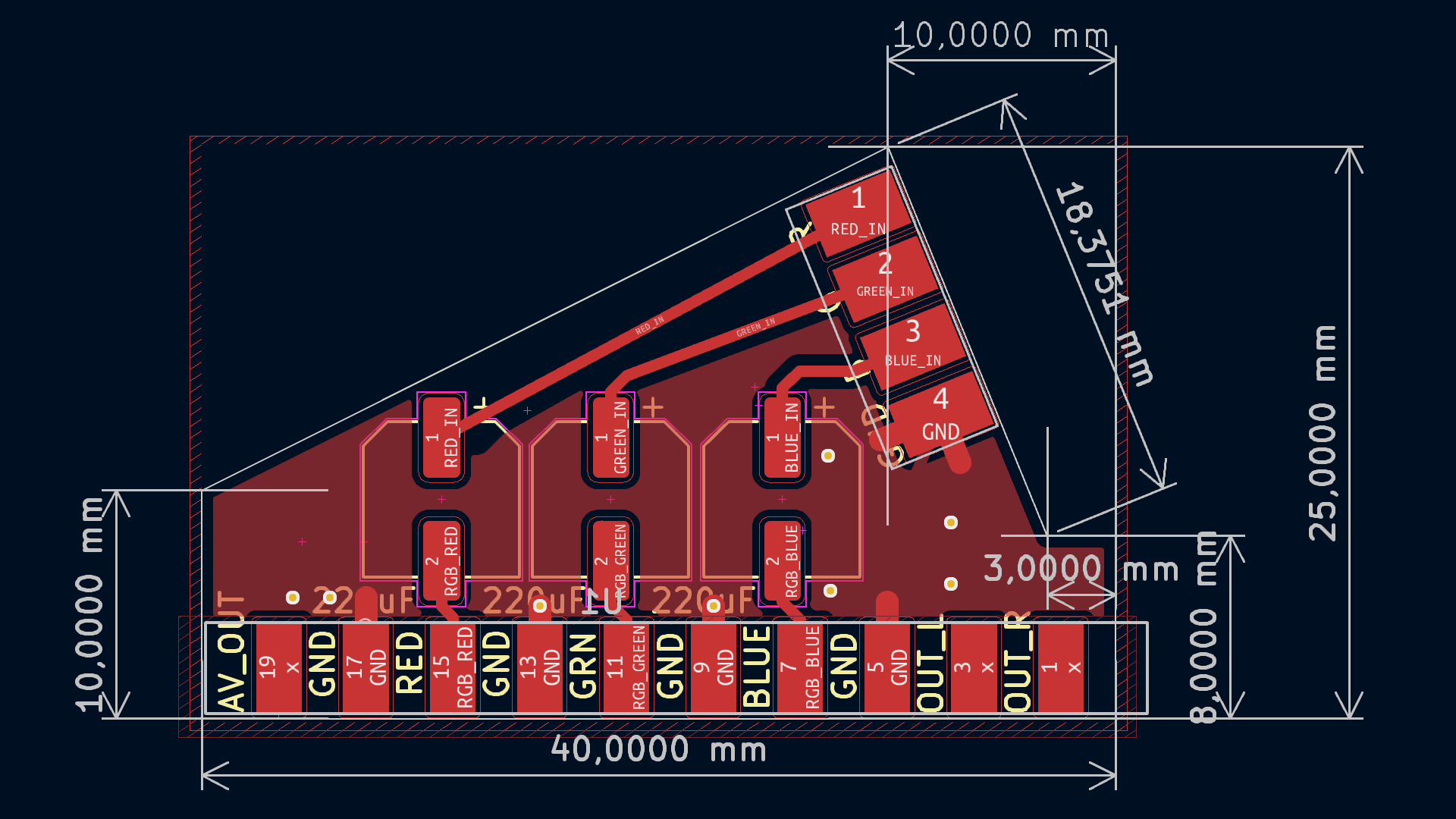
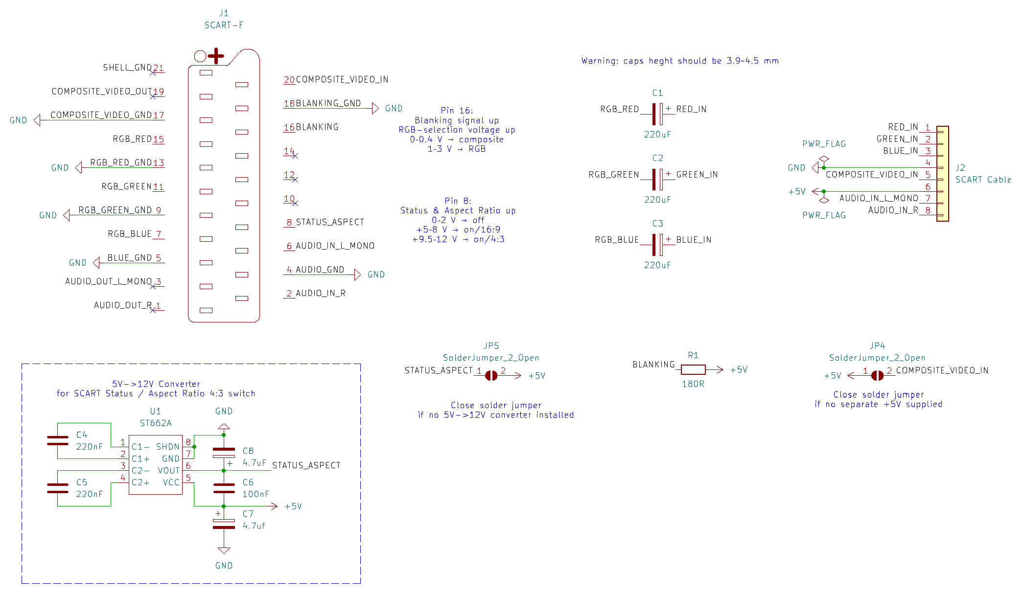
SCART RGB cable breakout PCB with ST662A 5V->12V converter
SCART Cable Breakout is an open-source printed circuit board by proboterror, from the proboterror/SCART_Cable_Breakout repository on GitHub. It is a 2-layer board of 40 × 25 mm with 14 parts on 23 nets, routed with 91 tracks and 8 vias.
Its parts include 8 capacitors, 2 connectors, 1 resistor and 1 IC. It belongs with the lEDs and displays and interfaces and adapters boards of this library.
SCART RGB cable breakout PCB with ST662A 5V->12V converter option for automatic SCART 4:3 aspect ratio switching.
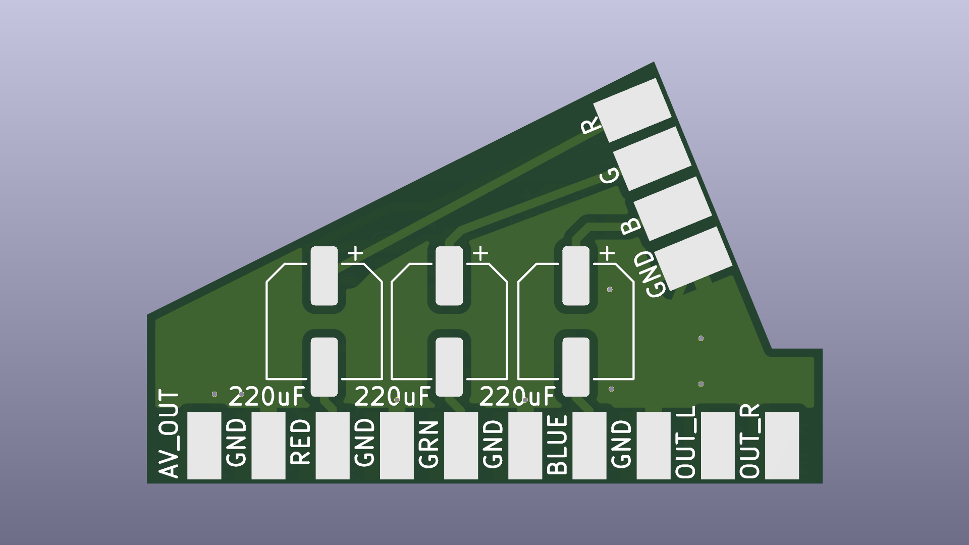
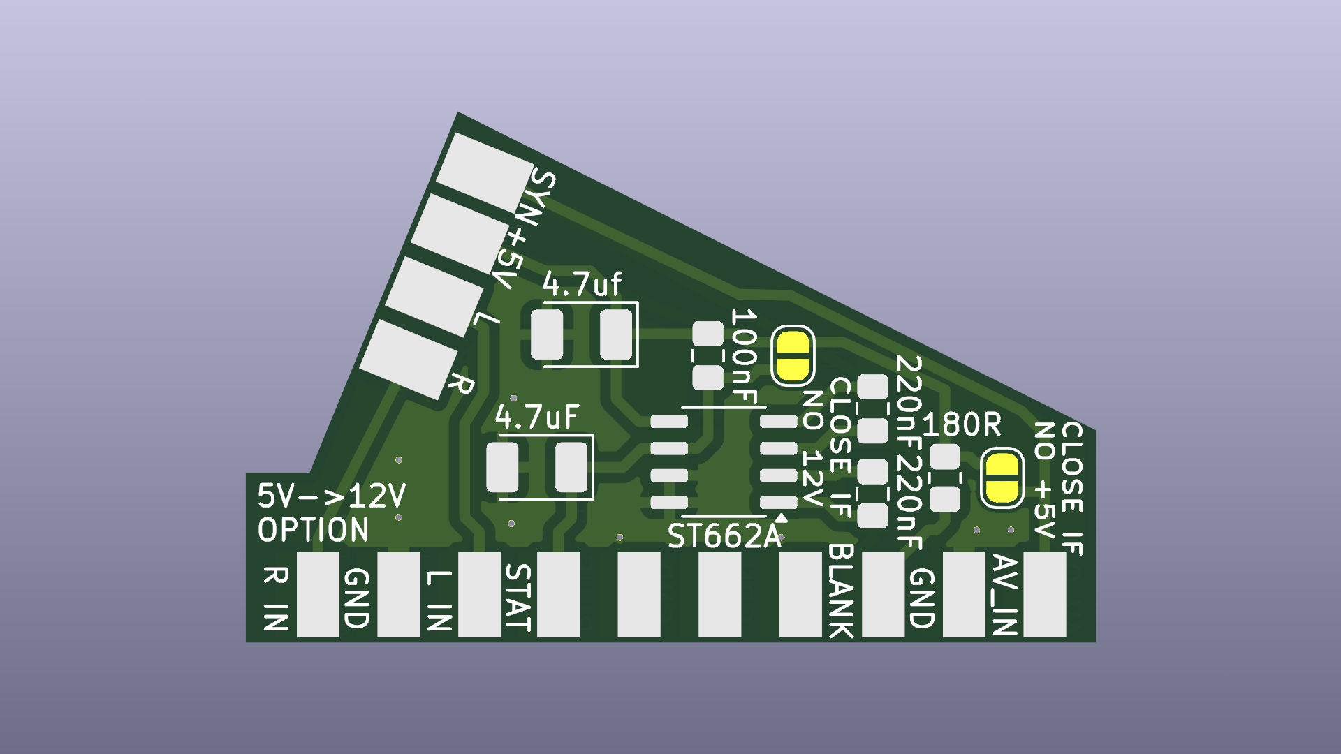
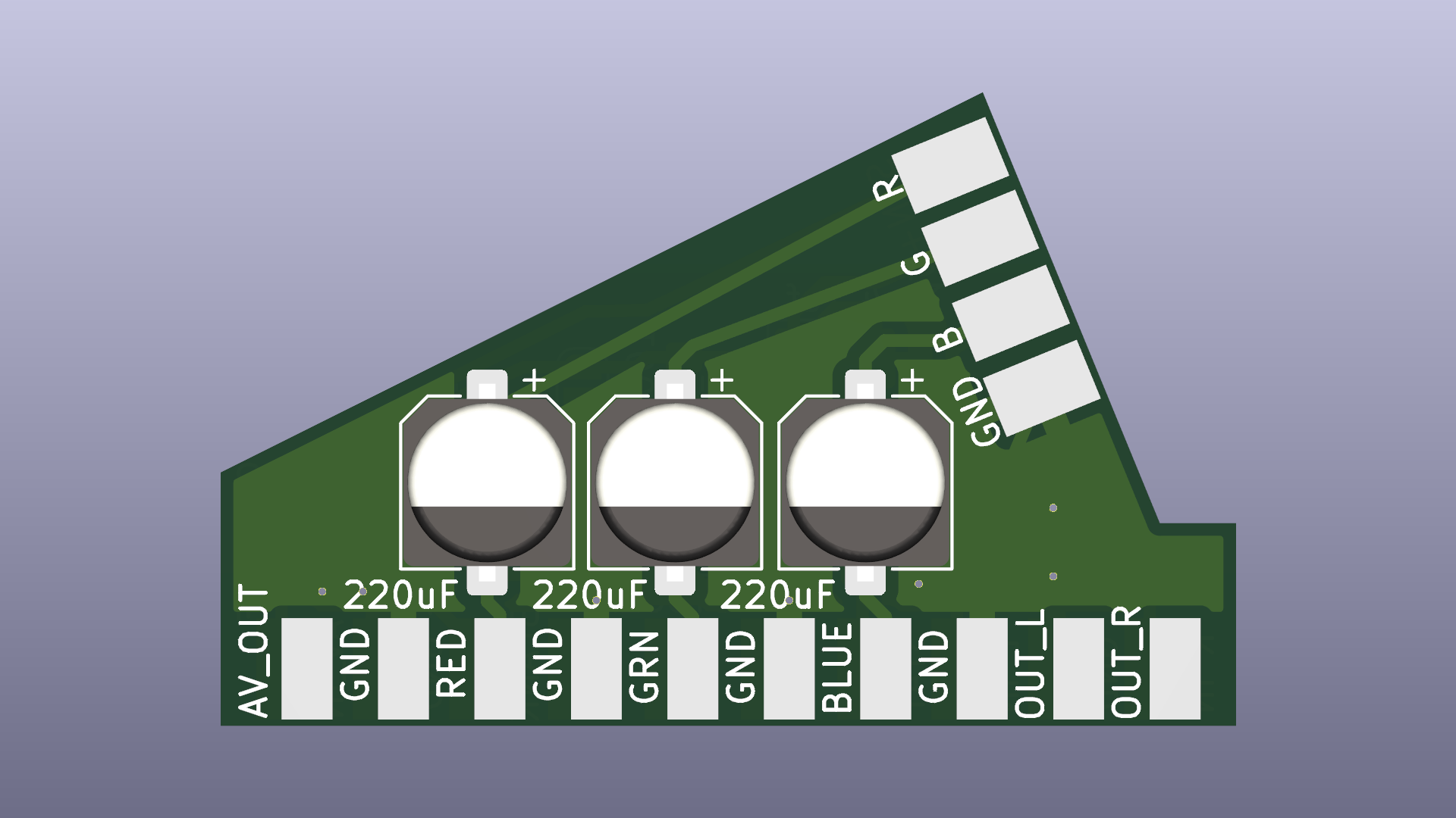
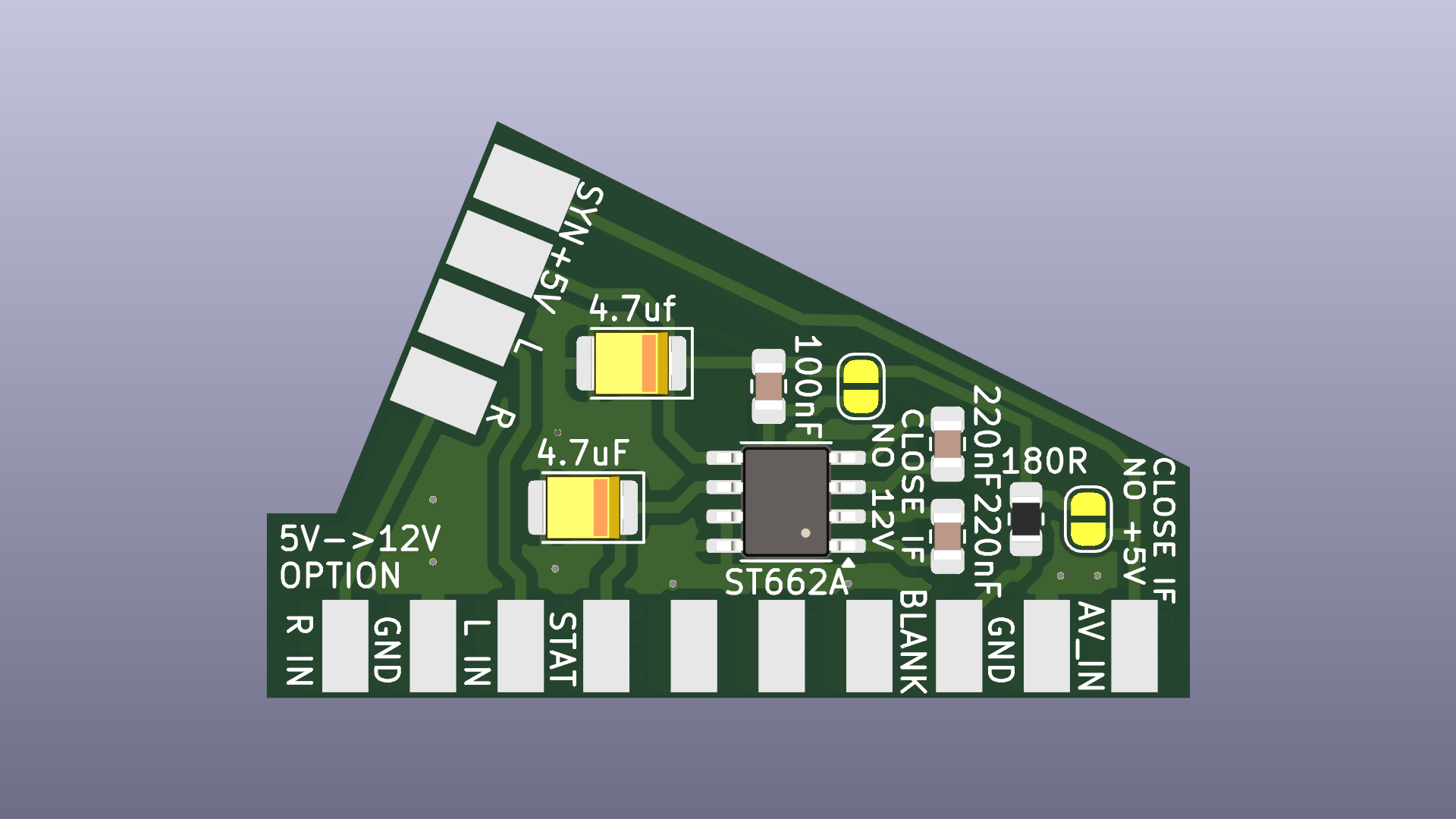
Reference from: fruitcake.plus.com/Sinclair/Spectrum128/SCARTCable
| Pin | Signal | Level |
|---|---|---|
| 8 | Function Switching | 0 to 2V = TV (default option if pin unconnected). 5 to 8V = TV wide screen. 9.5 to 12V = AV mode. >10k input impedance [When an AV source becomes active it sets 12V on pin 8 and causes the TV to automatically switch to that SCART input. When the source stops, the signal returns to 0V and TV viewing is resumed. If a 16:9 program is present, the source raises the signal on pin 8 to only 5V.] |
| 16 | Blanking | 75 ohm input and output impedance. 0V to 0.4V: TV is driven by the composite video input signal on pin 20, with transparent overlay of the Red, Green and Blue signals (default option if pin unconnected). 1V to 3V: TV is driven by the Red, Green, Blue signals and composite sync signal on pin 20. |
| 20 | Video Input (Luminance Input) | 1V [sync 0V - 0.3V, data 0.3V - 1V], 75 ohm input impedance (1V including sync, 75 ohm output impedance) |
The FUNCTION SWITCHING signal (pin 8) is used to instruct the TV set to automatically switch to show the SCART input, and the BLANKING signal (pin 16) is used to inform the TV set whether to show a composite video or RGB signal from that SCART socket. If the BLANKING signal is left disconnected then composite video is the default AV input type. If the FUNCTION SWITCHING signal is left disconnected then the AV input must be selected manually. The table below shows the different permutations:
| FUNCTION SWITCHING (Pin 8) | BLANKING (Pin 16) | TV Mode |
|---|---|---|
| 0V - 2V | 0V - 0.4V | Composite Video, Manual Selection |
| 0V - 2V | 1V - 3V | RGB, Manual Selection |
| 9.5V - 12V | 0V - 0.4V | Composite Video, Automatic Selection |
| 9.5V - 12V | 1V - 3V | RGB, Automatic Selection |
Send "gerbers" folder content packed to zip archive.
Be aware when ordering SMD capacitors: they should be minimal height 3.9 ~ 4.5 mm, depending on specific SCART connector. Or use A,B,C size tantalum capacitors.
180 Ohms resistor always should be soldered.
Bridge solder jumper if no separate +5V line supplied (composite sync / composite video signal used as power source for RGB selection / Status & Aspect Ratio pins).
Bridge solder jumper if no 5V->12V converter option installed (connect power to Status & Aspect Ratio pins).
Cable intended to be fixed inside connector housing with nylon strap.
| Qty | Value | Footprint | References |
|---|---|---|---|
| 3 | 220uF | Capacitor_SMD:CP_Elec_6.3x3.9 | C1, C2, C3 |
| 2 | 220nF | Capacitor_SMD:C_0805_2012Metric_Pad1.18x1.45mm_HandSolder | C4, C5 |
| 2 | SolderJumper_2_Open | Jumper:SolderJumper-2_P1.3mm_Open_RoundedPad1.0x1.5mm | JP4, JP5 |
| 1 | 100nF | Capacitor_SMD:C_0805_2012Metric_Pad1.18x1.45mm_HandSolder | C6 |
| 1 | 180R | Resistor_SMD:R_0805_2012Metric_Pad1.20x1.40mm_HandSolder | R1 |
| 1 | 4.7uF | Capacitor_Tantalum_SMD:CP_EIA-3528-21_Kemet-B_Pad1.50x2.35mm_HandSolder | C8 |
| 1 | 4.7uf | Capacitor_Tantalum_SMD:CP_EIA-3528-21_Kemet-B_Pad1.50x2.35mm_HandSolder | C7 |
| 1 | SCART Cable | SCART:SCART_In | J2 |
| 1 | SCART-F | SCART:SCART_Cutdown | J1 |
| 1 | ST662A | Package_SO:SO-8_3.9x4.9mm_P1.27mm | U1 |
It measures 40 × 25 mm and has 2 copper layers, 1.6 mm thick.
14 parts. The full list of its parts is on this page, with links to each part's symbol and footprint where PCBKit's library has them.
From the proboterror/SCART_Cable_Breakout repository on GitHub, at the commit this page was made from: the board is KiCad/SCART_Cable_Breakout.kicad_pcb and its schematic KiCad/SCART_Cable_Breakout.kicad_sch. PCBKit opens the board in the browser, with nothing to install.
Its repository states no licence, so its author keeps all rights: ask proboterror before reusing the design.
google/mozc-devices
Circuit diagrams and firmware source code for Gboard DIY keyboards


hackclub/OnBoard
💡 Join 1,000 teenagers and make your first PCB with a $100 grant!


Twotoz/C5VRX
Ultra-minimal, zero-CPU 5.8 GHz analog FPV video receiver using ESP32-C5 Wi-Fi 6 PHY MODEM_DIAG, BitScrambler WBFM demodulation & resistor DAC CVBS

