4 layers169.7 × 99.1 mm
RemoteLabs supervisor PCB
practable/supervisor-pcb
Allow students to program a remote labs experiment themselves, while protecting hardware from damage due to misfunction
201 parts
 practable/supervisor-pcb
Allow students to program a remote labs experiment themselves, while protecting hardware from damage due to misfunction
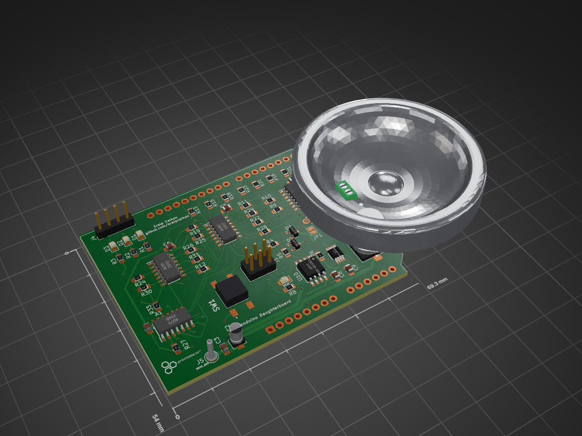
Driver PCB Vol3 is an open-source printed circuit board by practable, from the practable/supervisor-pcb repository on GitHub. It is a 2-layer board of 69.3 × 54 mm with 66 parts on 67 nets, routed with 561 tracks and 88 vias.
It is built around the ATTINY85-20SU, MAX9928FAUA+ and BC547, with the BC557 among its other parts. Its parts include 33 resistors, 9 capacitors, 6 ICs, 5 diodes and 5 connectors. It belongs with the AVR (ATmega, ATtiny) boards of this library.


NOTE: This project has been continued in a new location, please see: rl-supervisor-two for the latest version of this project
Design a PCB to provide power to remote labs experiments, which involve students programming microcontrollers remotely. PCB should also provide a supervisory role, blocking actuation of experimental hardware if it is likely to cause damage to the equipment.
This allows students to upload their own code to a bare bones microcontroller, without risk of causing hardware damage or unsafe conditions.

This document is intended to be a useage guide for the Remote Labs Supervisor PCB, and document the different use cases and configurations it is capable of.
For coded examples of the various features please see PCB Unit Tests, which contains arduino code firmware used during testing all hardware features of the PCB.
For the purposes of this document, it is assumed that the Motherboard PCB is populated with both Arduino Nano IoT 33 Daughterboards (A1 & A2), with shift registers installed, and NOT the bare bones SAMD21 MCU. A seperate document will be provided for cases in which SAMD21 MCUs are mounted to the motherboard directly.
All MCU pins will be referenced by the Arduino Pin Numbers in this document. Additional pins are sourced via Shift Registers attached to each MCU. Shift Register pins are labelled as Q0 - Q7. Both MCU connections to their independent shift registers are detailed below.
| MCU Pin | Shift Register Function |
|---|---|
| D8 | LATCH (Write to Register) |
| D11 | MOSI (Data) |
| D13 | SCK |
Complete pinout diagrams for both MCUs and Shift Registers can be found at the bottom of this document
The System should be provided 12v DC power via the yellow XT60 connector J3. The system is specified to draw a maximum of ~ 8A depending on experiment configuration, ensure that power supply selected is sufficient for specific use case.
Diode D6 (Blue) will light to show correct polarity power is provided to input. Diode D7 (Orange) will light to show 3V3 DC power is available to microcontrollers and periferal devices.
Motherboard has reverse polarity protection, however care should be taken to ensure correct orientation of power input. - NOTE: Currently missing protection diode- awaiting delivery
Each MCU, supervisor and student are able to be programmed via the USB connector on the daughterboard, or via UART using the 5 pin headers J26 Student_Prog_Header, and J1 Super_Prog_header.
For UART Programming, a hat is provided for raspi GPIO pins. 5 pin cable should be connected from Raspi hat to UART Programming connector on motherboard.
The USB connectors mounted to the Motherboard should not be used if Arduino Development boards are installed, and are UNTESTED for use with bare bones MCUs installed
In this configuration the following modules should be mounted to the motherboard:
In this configuration the following external hardware should be connected as follows:
DC Motor PWM is routed to Infineon DC Motor Controller module via the following logic:

If MOTOR_DIR_A is driven HIGH, PWM is routed from STUDENT_MOTOR_PWM or SUPERVISOR_MOTOR_PWM to MOTOR_OUT_1 If MOTOR_DIR_B is driven HIGH, PWM is routed from STUDENT_MOTOR_PWM or SUPERVISOR_MOTOR_PWM to MOTOR_OUT_2
Care must be taken to avoid driving MOTOR_DIR_A and MOTOR_DIR_B to HIGH at the same time as this will cause shoot through.
In Order to avoid shoot through condition, Student does not have direct input to MOTOR_DIR_A or MOTOR_DIR_B. These outputs are spoofed via the Supervisor MCU.
The MCU able to pass PWM signal to Motor Control Module is selected by MCU_MOTOR_SELECT pin. When HIGH - STUDENT_MOTOR_PWM is active, when LOW - SUPERVISOR_MOTOR_PWM is active.
In order to enable the DC Motor Control Module, OUT_M_ENABLE must also be set HIGH. This is routed from either MCU using the same logic as above, when MCU_MOTOR_SELECT is HIGH, ENABLE is routed from STUDENT_MOTOR_EN, when it is set LOW, ENABLE is routed from SUPERVISOR_MOTOR_EN.
M_I_SENSE_1 and M_I_SENSE_2 output is buffered and distributed to both MCUs.
Supervisor MCU uses the following table for DC Motor Control:
| MCU | Pin | Pin Name | State | Motor Behaviour | Notes |
|---|---|---|---|---|---|
| SUPERVISOR | D12 | MOTOR_DIR_1 | HIGH or LOW | Sets motor Direction | IF(D7 == HIGH){D12 MUST = LOW) |
| SUPERVISOR | D7 | MOTOR_DIR_2 | LOW or HIGH | Sets motor Direction | IF(D12 == HIGH){D7 MUST = LOW) |
| SUPERVISOR | Q0 | DC_MOTOR_EN | HIGH | Enables DC Motor Drive | |
| SUPERVISOR | Q1 | STUDENT_M_EN | LOW | Blocks Student Control, Enables Supervisor Control | |
| SUPERVISOR | A7 | DC_MOTOR_IS1 | ANALOG INPUT | Current Draw and Fault Condition Detection | |
| SUPERVISOR | A6 | DC_MOTOR_IS2 | ANALOG INPUT | Current Draw and Fault Condition Detection |
Student MCU uses the following table for DC Motor Control: Note - Student control relys on specific pin configurations of Supervisor MCU
| MCU | Pin | Pin Name | State | Motor Behaviour | Notes |
|---|---|---|---|---|---|
| STUDENT | D12 | MOTOR_DIR_1 | HIGH or LOW | Detected by Supervisor PIN A1 | IF(D7 == HIGH){D12 MUST = LOW) |
| STUDENT | D7 | MOTOR_DIR_2 | LOW or HIGH | Detected by Supervisor PIN A0 | IF(D12 == HIGH){D7 MUST = LOW) |
| STUDENT | Q0 | DC_MOTOR_EN | HIGH | Enables DC Motor Drive | |
| SUPERVISOR | Q1 | STUDENT_M_EN | HIGH | Blocks Supervisor Control, Enables Student Control | |
| SUPERVISOR | A1 | STDNT_DC_M_DIR_1 | DIGITAL INPUT | Detects state of Student Direction Pin and Spoofs output if logic != illegal | |
| SUPERVISOR | A0 | STDNT_DC_M_DIR_2 | DIGITAL INPUT | Detects state of Student Direction Pin and Spoofs output if logic != illegal | |
| SUPERVISOR | D12 | MOTOR_DIR_1 | HIGH or LOW | Sets motor Direction - Spoofed from A1 | |
| SUPERVISOR | D7 | MOTOR_DIR_2 | LOW or HIGH | Sets motor Direction - Spoofed from A0 | |
| STUDENT | A7 | DC_MOTOR_IS1 | ANALOG INPUT | Current Draw and Fault Condition Detection | |
| STUDENT | A6 | DC_MOTOR_IS2 | ANALOG INPUT | Current Draw and Fault Condition Detection |
Optical encoder signals are buffered and provided to both MCUs simaltaniously, therefore getting useful data from Optical Encoder is the same process for both MCUs
MCUs use the following table for Optical Encoder detection:
| MCU | Pin | Pin Name | State | Notes |
|---|---|---|---|---|
| Both | D2 | ENCODER_B | EXTERNAL INTERRUPT / DIGITAL INPUT | For best performance, External Interrupt used for edge detection of Encoder waveform |
| Both | D3 | ENCODER_A | EXTERNAL INTERRUPT / DIGITAL INPUT | Alternative pin for External Interrupt. |
| Both | D4 | ENCODER_INDEX | DIGITAL INPUT | Used to track center detent of optical encoder (Untested in software) |
In this configuration the following modules should be mounted to the motherboard:
DC Motor & Optical Encoder are accessed as Use Case 1 above
In this configuration the following external hardware should be connected as follows:
Stepper Motor Driver inputs are routed via the following logic:

When MCU_STEP_SELECT is HIGH, inputs are routed from STUDENT MCU. When MCU_STEP_SELECT is LOW, inputs are routed from SUPERVISOR MCU.
STEPP_EN is driven from Supervisor MCU Only, however does not seem to have any effect on stepper motor function. - Requires further investigation.
STEPPR_FAULT output is buffered and distributed to both MCUs.
LIMIT_1 Limit switch input is buffered and distributed to both MCUs.
Supervisor MCU uses the following table for Stepper Motor Control:
| MCU | Pin | Pin Name | State | Motor Behaviour | Notes |
|---|---|---|---|---|---|
| SUPERVISOR | D6 | STEPP_STEP | PULSE | Motor advances 1 step per pulse | |
| SUPERVISOR | Q2 | STUDENT_STEP_EN | LOW | Blocks Student Control, Enables Supervisor Control | |
| SUPERVISOR | Q4 | STEPP_DIR | HIGH or LOW | Sets Stepper Motor Direction | |
| SUPERVISOR | Q5 | STEPP_SLP | HIGH or LOW | Enables and Sleeps motor to avoid overheating | MUST BE HIGH? to enable |
| SUPERVISOR | Q6 | STEPP_RST | HIGH or LOW | Resets controller board after fault condition | MUST BE HIGH? to enable |
| SUPERVISOR | Q7 | STEPP_EN | HIGH or LOW | Enables motor driver board | NO DECERNABLE EFFECT? - Needs Testing |
| SUPERVISOR | A5 | STEPP_FLT | DIGITAL INPUT | Fault reporting from Stepper Control daughterboard | HIGH = NO FAULT, LOW = FAULT |
| SUPERVISOR | A4 | LIMIT_1 | DIGITAL INPUT | Limit Switch Detection. | LOW = Switch Pressed |
Student MCU uses the following table for Stepper Motor Control: Note - Student control relys on specific pin configurations of Supervisor MCU
| MCU | Pin | Pin Name | State | Motor Behaviour | Notes |
|---|---|---|---|---|---|
| STUDENT | D6 | STEPP_STEP | PULSE | Motor advances 1 step per pulse | |
| SUPERVISOR | Q2 | STUDENT_STEP_EN | HIGH | Enables Student Control, Blocks Supervisor Control | |
| STUDENT | Q4 | STEPP_DIR | HIGH or LOW | Sets Stepper Motor Direction | |
| STUDENT | Q5 | STEPP_SLP | HIGH or LOW | Enables and Sleeps motor to avoid overheating | MUST BE HIGH? to enable |
| STUDENT | Q6 | STEPP_RST | HIGH or LOW | Resets controller board after fault condition | MUST BE HIGH? to enable |
| SUPERVISOR | Q7 | STEPP_EN | HIGH or LOW | Enables motor driver board | NO DECERNABLE EFFECT? - Needs Testing |
| STUDENT | A5 | STEPP_FLT | DIGITAL INPUT | Fault reporting from Stepper Control daughterboard | HIGH = NO FAULT, LOW = FAULT |
| STUDENT | A4 | LIMIT_1 | DIGITAL INPUT | Limit Switch Detection. | LOW = Switch Pressed |
SW1 - Stepper Mode Dipswitches set number of steps per revolution. If UNPOPULATED setting is at MAX RESOLUTION. (1, 1, 1 ) logic for MODE inputs.
In this configuration the following modules should be mounted to the motherboard:
DC Motor & Optical Encoder are accessed as Use Case 1 above
In this configuration the following external hardware should be connected as follows:
In this use case, supervisor must calibrate and track the position of DC motor to avoid equipment collision with self.
Supervisor has ultimate control of the Servo PPM output.
Supervisor MCU uses the following table for Servo Motor Control:
| MCU | Pin | Pin Name | State | Motor Behaviour | Notes |
|---|---|---|---|---|---|
| SUPERVISOR | D9 | SERVO_1 | PPM Output | PPM Standard sets Servo Position |
Student MCU has no direct output to servo_1, instead supervisor must spoof and constrain output; given either a PWM signal, or PPM signal from the Student, applied to Pin A2 of the supervisorU MCU.
Student MCU uses the following table for Servo Motor Control: Note - Student control relys on specific pin configurations of Supervisor MCU
| MCU | Pin | Pin Name | State | Motor Behaviour | Notes |
|---|---|---|---|---|---|
| STUDENT | D9 | SERVO_1 | PPM or PWM Output | PPM/PWM used to infer desired position of servo | |
| SUPERVISOR | A2 | STDNT_SRVO_RX_1 | ANALOG INPUT or EXTERNAL INTERRUPT | Detects infered desired position for servo | |
| SUPERVISOR | D9 | SERVO_1 | PPM Output | PPM Standard sets Servo Position |
NOTE: USE CASE UNTESTED
In this configuration the following modules should be mounted to the motherboard:
In this configuration the following external hardware should be connected as follows:
Supervisor MCU uses the following table for Pendulum Control:
| MCU | Pin | Pin Name | Pendulum PCB Pin Name | State | Pendulum Behaviour | Notes |
|---|---|---|---|---|---|---|
| SUPERVISOR | Q0 | DC_MOTOR_EN | ENABLE | DIGTAL OUTPUT | Drive | Tried to avoid this being on a shift register - failed can it be moved to another pin? User Thermo A3, and enable |
| SUPERVISOR | D6 | STEPP_STEP | PENDULUM_PIN_1 | DIGTAL OUTPUT | Load | |
| SUPERVISOR | D12 | DC_MOTOR_DIR_1 | PENDULUM_PIN_7 | DIGTAL OUTPUT | LED_1 Control | |
| SUPERVISOR | D7 | DC_MOTOR_DIR_2 | PENDULUM_PIN_8 | DIGTAL OUTPUT | LED_2 Control | |
| SUPERVISOR | D9 | SERVO_1 | PENDULUM_PIN_6 | DIGTAL OUTPUT | LED_3 Control | |
| SUPERVISOR | Q1 | STUDENT_M_EN | PENDULUM_PIN_2 | LOW | Blocks Student Control, Enables Supervisor Control | |
| SUPERVISOR | A7 | DC_MOTOR_IS1 | I_SENSE_1 | ANALOG INPUT | Current Draw and Fault Condition Detection | Check which way around these are |
| SUPERVISOR | A6 | DC_MOTOR_IS2 | I_SENSE_2 | DIGITAL INPUT | Current SIGN reporting (+/-) | HIGH = Positive Current, LOW = Negative Current |
Student MCU uses the following table for Stepper Motor Control: Note - Student control relys on specific pin configurations of Supervisor MCU
| MCU | Pin | Pin Name | Pendulum PCB Pin Name | State | Pendulum Behaviour | Notes |
|---|---|---|---|---|---|---|
| STUDENT | Q0 | DC_MOTOR_EN | ENABLE | DIGTAL OUTPUT | Drive | Tried to avoid this being on a shift register - failed can it be moved to another pin? User Thermo A3, and external enable |
| STUDENT | D6 | STEPP_STEP | PENDULUM_PIN_1 | DIGTAL OUTPUT | Load | |
| STUDENT | A0 | SPARE_0 | PENDULUM_PIN_3 | DIGTAL OUTPUT | LED_1 Control | |
| STUDENT | A1 | SPARE_1 | PENDULUM_PIN_4 | DIGTAL OUTPUT | LED_2 Control | |
| STUDENT | A2 | SPARE_2 | PENDULUM_PIN_5 | DIGTAL OUTPUT | LED_3 Control | |
| SUPERVISOR | Q1 | STUDENT_M_EN | PENDULUM_PIN_2 | HIGH | Enables Student Control, Blocks Supervisor Control | |
| STUDENT | A7 | DC_MOTOR_IS1 | I_SENSE_1 | ANALOG INPUT | Current Draw and Fault Condition Detection | Check which way around these are |
| STUDENT | A6 | DC_MOTOR_IS2 | I_SENSE_2 | DIGITAL INPUT | Current SIGN reporting (+/-) | HIGH = Positive Current, LOW = Negative Current |
To use WS2812 LED strips with any configuration, the following external hardware should be connected as follows:
Supervisor MCU uses the following table for WS2812B LED Control.
| MCU | Pin | Pin Name | State | Use | Notes |
|---|---|---|---|---|---|
| SUPERVISOR | D5 | PIXEL_DATA | DIGITAL OUTPUT | Sets LED Colour & Brightness | |
| SUPERVISOR | Q3 | STUDENT_PIXEL_EN | LOW | Blocks Student Control, Enables Supervisor Control |
Student MCU uses the following table for WS2812B LED Control.: Note - Student control relys on specific pin configurations of Supervisor MCU
| MCU | Pin | Pin Name | State | Use | Notes |
|---|---|---|---|---|---|
| STUDENT | D5 | PIXEL_DATA | DIGITAL OUTPUT | Sets LED Colour & Brightness | |
| SUPERVISOR | Q3 | STUDENT_PIXEL_EN | HIGH | Enables Student Control, Blocks Supervisor Control |
| Voltage/Bus | Purpose/Name | Component Number | Connector Type | Current Considerations |
|---|---|---|---|---|
| 12V | 12V_DC | J30 | Screw Terminal | Unregulated ~8A Max(For entire Bus) |
| 12V | Strip Lighting | J4 | Molex | Unregulated ~8A Max(For entire Bus) |
| 12V | DC MOTOR PWR | J16 | Screw Terminal | Unregulated ~8A Max(For entire Bus) |
| 5V_DC_LED | 5V_DC_LED | J6 | Screw Terminal | 1A Total. Regulated |
| 5V_DC_RPI | 5V_DC Spare | J31 | Screw Terminal | 2.5A Total. Regulated |
| 5V_DC_RPI | USB Power | J5 | USB A Socket x2 | 2.5A Total. Regulated |
Additional headers have been provided for:
These are intended for future use, fault finding or reconfirging PCBs to perform tasks outside of the specified use cases.
Currently Unavailable due to parts shortages
To use Thermocouple Input with any configuration, the following external hardware should be connected as follows:
Thermocouple input J22 Thermocouple requires IC U19 AD8497 To be populated. (UNTESTED)
Analog voltage is buffered and distributed to both MCUs, Pin A3
MCU and Shift Register Pinout diagrams


| Qty | Value | Footprint | References |
|---|---|---|---|
| 25 | 10k | Resistor_SMD:R_0805_2012Metric_Pad1.20x1.40mm_HandSolder | R10, R11, R12, R13, R14, R15, R16, R17, R18, R19, R20, R21, R22, R23, R24, R25 +9 |
| 5 | 0.1uF | Capacitor_SMD:C_0805_2012Metric_Pad1.18x1.45mm_HandSolder | C4, C5, C6, C7, C9 |
| 4 | LED | LED_SMD:LED_0805_2012Metric_Pad1.15x1.40mm_HandSolder | D1, D2, D3, D5 |
| 2 | 2k2 | Resistor_SMD:R_0805_2012Metric_Pad1.20x1.40mm_HandSolder | R4, R5 |
| 2 | 330 | Resistor_SMD:R_0805_2012Metric_Pad1.20x1.40mm_HandSolder | R1, R2 |
| 2 | 4011 | Package_SO:SOIC127P600X175-14N | U2, U3 |
| 2 | 680 | Resistor_SMD:R_0805_2012Metric_Pad1.20x1.40mm_HandSolder | R3, R8 |
| 2 | NetTie_2 | NetTie:NetTie-2_SMD_Pad0.5mm | NT1, NT2 |
| 1 | 0.1u | Capacitor_SMD:C_0805_2012Metric_Pad1.18x1.45mm_HandSolder | C3 |
| 1 | 100k | Resistor_SMD:R_0805_2012Metric_Pad1.20x1.40mm_HandSolder | R6 |
| 1 | 100nF | Capacitor_SMD:C_0805_2012Metric_Pad1.18x1.45mm_HandSolder | C8 |
| 1 | 10R | Resistor_SMD:R_0805_2012Metric_Pad1.20x1.40mm_HandSolder | R7 |
| 1 | 10u | Capacitor_SMD:CP_Elec_3x5.3 | C2 |
| 1 | 1N4002 | Diode_THT:D_T-1_P5.08mm_Horizontal | D4 |
| 1 | 4071 | Package_SO:SOIC127P600X175-14N | U4 |
| 1 | 4081 | Package_SO:SOIC127P600X175-14N | U1 |
| 1 | 470u | Capacitor_SMD:C_Elec_8x10.2 | C1 |
| 1 | ATtiny85-20S | Package_SO:SOIC-8W_5.3x5.3mm_P1.27mm | U10 |
| 1 | AVR-ISP-6 | Connector_PinHeader_2.54mm:PinHeader_2x03_P2.54mm_Vertical | J1 |
| 1 | BC547 | Package_TO_SOT_SMD:SOT-23 | Q2 |
| 1 | BC557 | Package_TO_SOT_SMD:SOT-23 | Q1 |
| 1 | Coil | Connector_Molex:RSPROPenduinoTerminal | J2 |
| 1 | Conn_01x04 | Connector_PinHeader_2.54mm:PinHeader_1x04_P2.54mm_Vertical | J4 |
| 1 | DRIVE_5V_IN | Connector_Pin:Pin_D1.3mm_L11.0mm | J7 |
| 1 | DRIVE_GND | Connector_Pin:Pin_D1.3mm_L11.0mm | J5 |
| 1 | Infineon Motor Shield MOD | Audio_Module:Infineon Motor Sheild hiddenPins | A1 |
| 1 | LOGO | 000_Graphics_Immo:practactable.io_text_10x4 | G*** |
| 1 | MAX9928FAUA+ | Sensor_Current:SOP65P490X110-8N | IC5 |
| 1 | SW_Push | Button_Switch_SMD:13019319 | SW1 |
| 1 | Shunt Bypass | Jumper:SolderJumper-2_P1.3mm_Open_Pad1.0x1.5mm | JP1 |
It measures 69.3 × 54 mm and has 2 copper layers, 1.6 mm thick.
66 parts, built around the ATTINY85-20SU, MAX9928FAUA+, BC547 and BC557. The full list of its parts is on this page, with links to each part's symbol and footprint where PCBKit's library has them.
From the practable/supervisor-pcb repository on GitHub, at the commit this page was made from: the board is Interns_PCBs/pendulum_daughterboard/Old Designs/Driver PCB Version 3/Driver PCB Vol3/Driver PCB Vol3.kicad_pcb. PCBKit opens the board in the browser, with nothing to install.
Its repository states no licence, so its author keeps all rights: ask practable before reusing the design.
practable/supervisor-pcb
Allow students to program a remote labs experiment themselves, while protecting hardware from damage due to misfunction

practable/supervisor-pcb
Allow students to program a remote labs experiment themselves, while protecting hardware from damage due to misfunction

practable/supervisor-pcb
Allow students to program a remote labs experiment themselves, while protecting hardware from damage due to misfunction

practable/supervisor-pcb
Allow students to program a remote labs experiment themselves, while protecting hardware from damage due to misfunction

practable/supervisor-pcb
Allow students to program a remote labs experiment themselves, while protecting hardware from damage due to misfunction

dotnet/iot
This repo includes .NET Core implementations for various IoT boards, chips, displays and PCBs.

robsonsmartins/usbflashprog
A memory device programmer (Flash/EPROM/E2PROM) board and software, connected to PC by USB port.


telec16/modular-synth
Little side project, don't expect much updates.

nodep/NovaBox
Circuit and PCB design of simple Bluetooth stereo receiver and amplifier

