2 layers56 × 65 mm
SeaTalk1
dotnet/iot
This repo includes .NET Core implementations for various IoT boards, chips, displays and PCBs.
24 parts2.4kMIT

 PotatoPerchance/binary_keyboard
Why do you need 40-50 keys when you know binary? Just type whatever your imagination holds one byte at a time :)
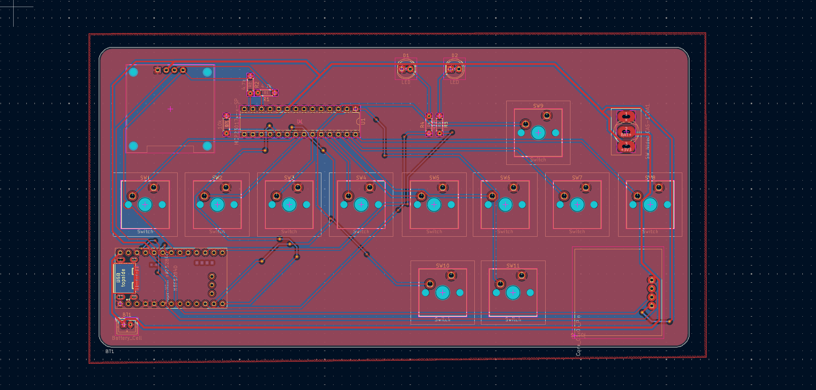
Binary keyboard is an open-source printed circuit board by PotatoPerchance, from the PotatoPerchance/binary_keyboard repository on GitHub. It is a 2-layer board of 175.8 × 89.4 mm with 24 parts on 53 nets, routed with 203 tracks and 22 vias.
Its parts include 12 switches, 5 resistors, 2 ICs, 2 diodes and 2 connectors. It belongs with the keyboards and input boards and the nRF52 and nRF5x boards of this library.
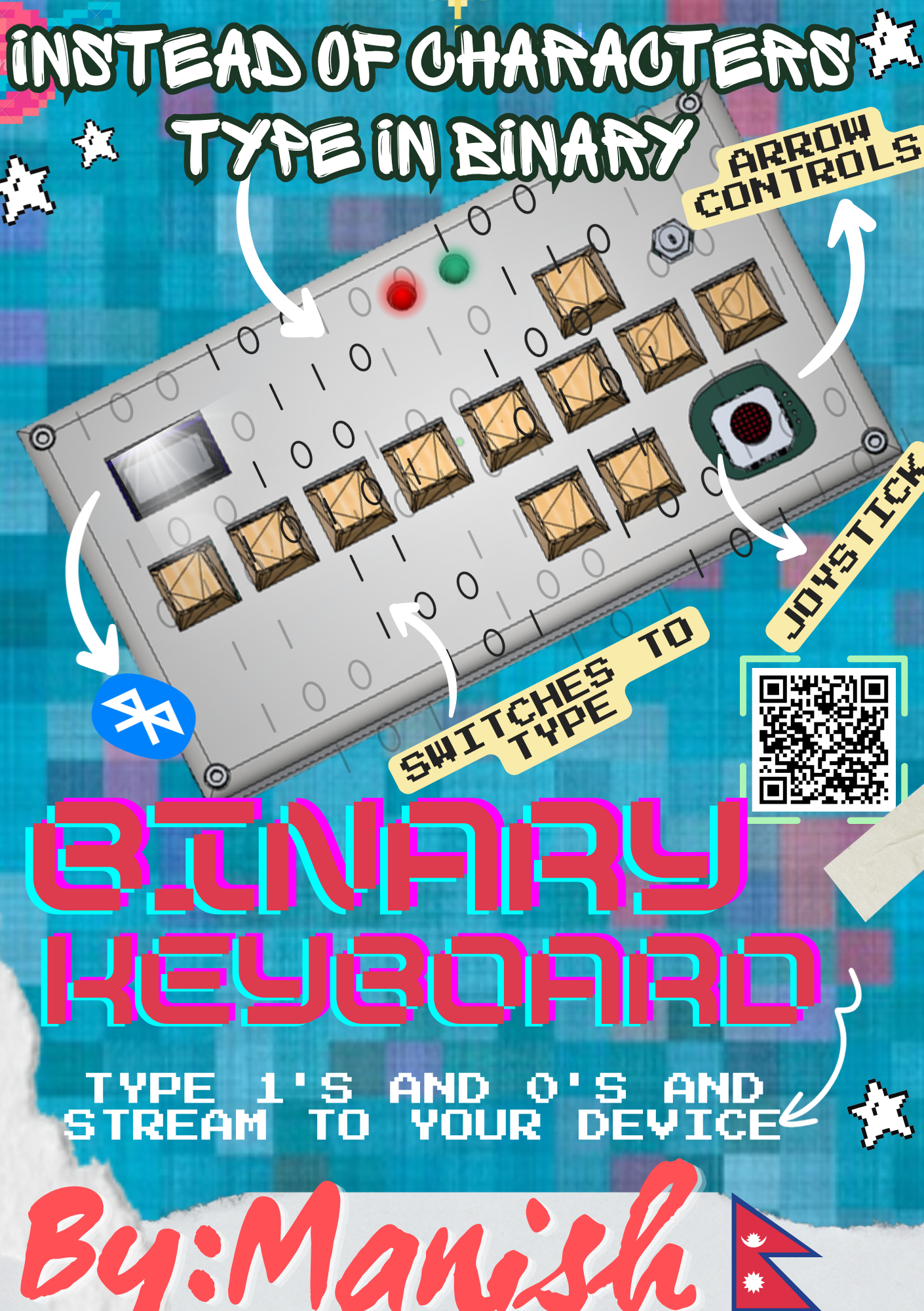
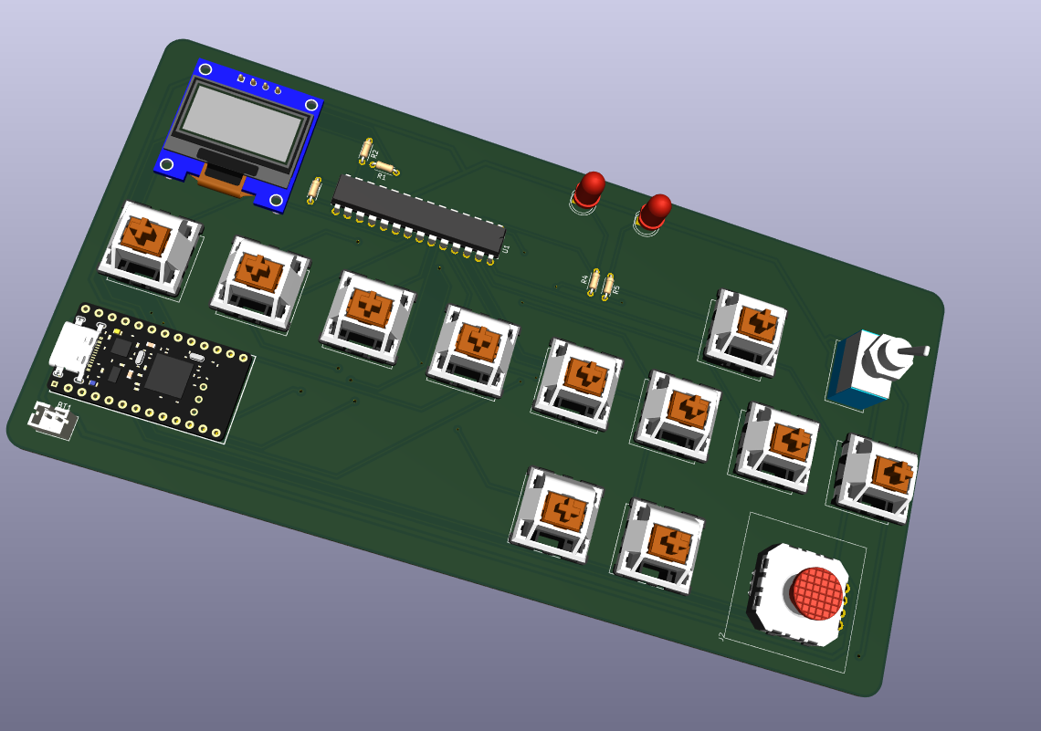
This is wacky, silly project where you can type your keyboard inputs in binary and send it to a connected device. You can enter the byte values (8 switches represent 8 bits in a byte) which represents a character. Then you confirm your input with the enter switch to covert that binary byte to a character to send to your device (wired or wireless!). Basically a keyboard but you type in binary because why not! It uses the SuperMini nRF52840 mcu ( a nice!nano clone) which supports bluetooth connectivity for you to send your inputs wirelessly.
I build the binary keyboard just for the sake of learning. No other motives. Its just a very stupid and fun idea which struck me and there I went building :)
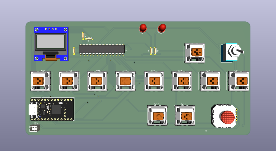
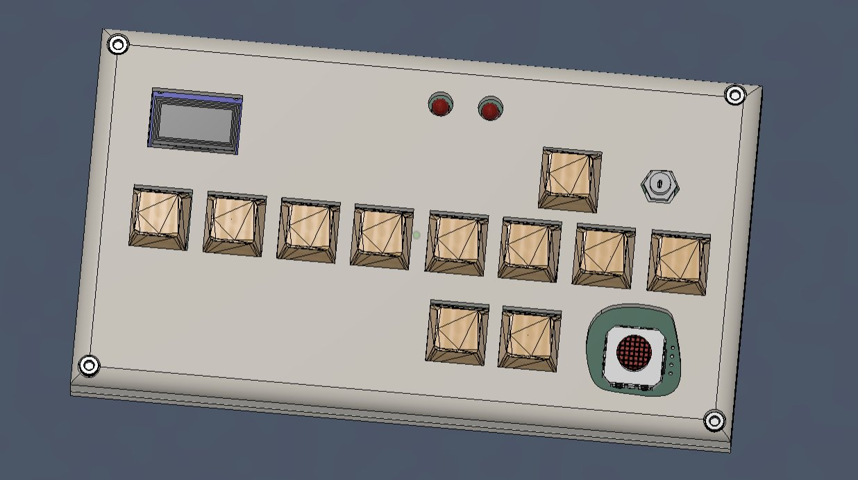
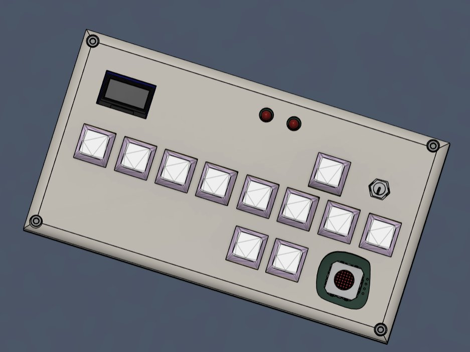
├── 📁 3d_models
│   ├── 📁 Fusion 360     # Contains the .f3d files and STEP files
│   └── 📁 PCB export     # The 3d file exported from KiCad
├── 📁 KiCad              # Contains the KiCad schematics and PCB files
├── 📁 Firmware
│   ├── 📁 Circuit Python # Contains the uf2 file that is to be flashed to the supermini
│   ├── 📁 lib            # Contains a zip file for the circuitpython firmware
│   └── 📄 code.py        # Contains the main code
└── 📁 BOM
    ├── 📄 kicad.csv      # KiCad generated CSV (no price present)
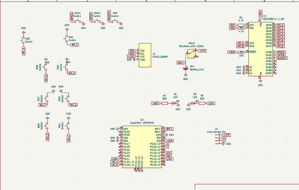
└── 📄 BOM.cBOM mnaully created with price and total estimationThere are an array of 8 switches that are connected to the GPA0 to GPA7 of the MCP23017 gpio expander. The GPB0 has three connections - (SPACE, BACKSPACE and ENTER). There are intrerrupts for both of them which are conencted to gpios of the mcu. Whenever a user presses a button (any of the 8 buttons that repsresnt 1 bit of a byte for a single char) the state is changed for that bit's value. So if it was a 0 it changes to 1. Like that we can toggle each of the bits state and at the end press the enter button to confirm the data input. Then the python script (code.py) converted the byte to a char by mapping it to a character and returns it to the USB_HID device for it to be printed on your screen.
First print the PCB. Print the 3d case. Then solder the parts in place. For the firmware- flash the uf2 file in the supermini. Then install the firmware into the mcy by unzippping the file inside /Firmware/lib. And upload the code.py file to begin testing and using the device.
For firmware guidance and the code.py file code. Teensy help on fusion on selecting screw and other minor stuff. And small help for debugging kicad schematic and suggestions for improvements.
| Qty | Value | Footprint | References |
|---|---|---|---|
| 11 | Switch | ScottoKeebs_MX:MX_PCB_1.00u | SW1, SW2, SW3, SW4, SW5, SW6, SW7, SW8, SW9, SW10, SW11 |
| 2 | 300 | Resistor_THT:R_Axial_DIN0204_L3.6mm_D1.6mm_P5.08mm_Horizontal | R4, R5 |
| 2 | 4.7k | Resistor_THT:R_Axial_DIN0204_L3.6mm_D1.6mm_P5.08mm_Horizontal | R1, R2 |
| 2 | LED | LED_THT:LED_D5.0mm | D1, D2 |
| 1 | 10k | Resistor_THT:R_Axial_DIN0204_L3.6mm_D1.6mm_P5.08mm_Horizontal | R3 |
| 1 | Battery_Cell | Connector_JST:JST_PH_B2B-PH-K_1x02_P2.00mm_Vertical | BT1 |
| 1 | Conn_01x04_Pin | small _yoystick:footprint25.8 * 25.8 | J2 |
| 1 | MCP23017x-x-SP | Package_DIP:DIP-28_W7.62mm | U1 |
| 1 | OLED_128x64 | ScottoKeebs_Components:OLED_128x64 | J1 |
| 1 | SW_Nidec_CAS-120A1 | Toggle switch:SW_Toggle_Blue_wSlots | SW12 |
| 1 | SuperMini nRF52840 | Supermini nrf52840:SuperMini NRF52840 | U2 |
It measures 175.8 × 89.4 mm and has 2 copper layers, 1.6 mm thick.
24 parts. The full list of its parts is on this page, with links to each part's symbol and footprint where PCBKit's library has them.
From the PotatoPerchance/binary_keyboard repository on GitHub, at the commit this page was made from: the board is KiCad/Binary_keyboard/Binary_keyboard.kicad_pcb and its schematic KiCad/Binary_keyboard/Binary_keyboard.kicad_sch. PCBKit opens the board in the browser, with nothing to install.
Its repository states no licence, so its author keeps all rights: ask PotatoPerchance before reusing the design.
dotnet/iot
This repo includes .NET Core implementations for various IoT boards, chips, displays and PCBs.

pascallanger/DIY-Multiprotocol-TX-Module
Multiprotocol TX Module (or MULTI-Module) is a 2.4GHz transmitter module which controls many different receivers and models.


rusefi/rusefi
rusefi - GPL internal combustion engine control unit

DraftShift/StealthChanger
Tool changing system for Vorons and other front mount printer motion systems, not just stealthburner.

VoronDesign/Voron-Hardware
Cool Hardware designed by the Voron Design group

hackclub/OnBoard
💡 Join 1,000 teenagers and make your first PCB with a $100 grant!
