2 layers252.7 × 106.7 mm

 polpo/imagescribbler14
A Clone of Apple's ImageWriter II/LQ LocalTalk Option card
Lt option clone is an open-source printed circuit board by polpo, from the polpo/imagescribbler repository on GitHub, published under the CC0-1.0 licence. It is a 2-layer board of 225.4 × 69.3 mm with 49 parts on 119 nets, routed with 1,595 tracks and 175 vias.
It is built around the 74HCT245, 74HCT367D and 74HCT374D, with the 74HCT00D, 74HCT74D and 74AHCT138D among its other parts. Its parts include 18 capacitors, 18 ICs, 3 resistors and 1 connector.


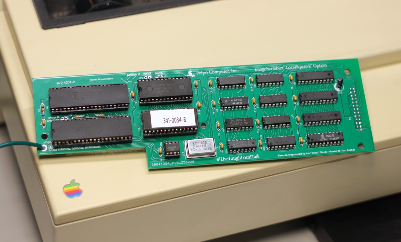
The ImageScribbler LocalSquawk option is a 1:1 clone of Apple's ImageWriter II/LQ LocalTalk Option card, with a few extra enhancements to make building one easier. It works and behaves in exactly the same way as Apple's original card.
This card can be used in an Apple ImageWriter II or LQ printer to enable LocalTalk networking.
Since this is a clone of an existing device, it's licensed CC0. Do whatever you want with it!
Want to buy one fully assembled or just a bare PCB? JCM-1 has them!
For information on how to use this card in an ImageWriter, Apple's original User Guide for the ImageWriter II/LQ LocalTalk Option is a good reference.
Apple's original card uses 74LS/74F series chips. While testing this board with a large number of salvaged 65C02/65SC02 chips, I've found that the 74HCT/74AHCT series chips are not only more compatible with a wider range of these CMOS chips, nowadays they are more available and cheaper. So I recommend using that series, and that is what is now specified in the BOM.
The connector specified in the BOM for P1 is pretty expensive due to its height. You can possibly use a shorter IDC-style connector, but be aware of clearance under the board and height of standoffs on the ImageWriter II, and on the ImageWriter LQ, it may not make sufficient contact with the connector inside the printer. On boards that I've made for sale, I use a PCB spacer along with the more commonly available shorter connector to get the proper height. Remember that P1 goes on the underside of the board, with the polarizing key facing towards the near edge of the board.
The capacitor for C18 in the BOM is short enough to fit with no clearance issues, but taller more commonly available capacitors can be used, just bend them over before soldering.
If you are using a 2K 6116 SRAM, bridge JP1 and ensure that the chip is aligned to the right side of the footprint, leaving the leftmost 4 pads open. An 8K 6264 SRAM (specified in the BOM) fills the entire footprint, and JP2 must be bridged.
This design can use either the (still available in 2025) WDC W65C02S, or vintage 65C02/64SC02 chips by other manufacturers. If using the WDC chip, bridge JP4 and leave JP3 open. If using any other chip, bridge JP3 and leave JP4 open.
You'll have to source vintage parts for the SCC (Zilog Z8530 or Z85C30, AMD AM8530 or AM85C30), NVSRAM (Xicor X2444 or X24C44 or CSI 24C44LI), and if you're not using a new WDC W65C02, the CPU (Rockwell/Conexant R65C02, CMD/GTE G65SC02, or NCR 65C02A).
Program the E[E]PROM at U4 with the 341-0034-B.bin ROM image available at the Apple II Documentation Project.
Program the NVSRAM at U18 with X2444-imagescribbler.bin in this repository. If this chip is not programmed, the card may not show up in Chooser, and it will not be able to be renamed by The Namer.
To bridge JP1/2/3/4 (set according to instructions above), you have three options: solder in part of the cut off leads from the resistors or capacitors, use a solder bridge, or if you want to make it configurable, use 2.54mm pin headers and jumper shunts.
While not strictly necessary, the original board uses a grounding wire from the plated through hole on the left side to to a spade lug inside the printer. I recommend connecting it as it really does clean up the ground on the board. Use a small length of wire with a crimp spade connector.
The original board came with standoffs to prevent it from contacting the main board inside the ImageWriter II, and matching standoffs are included in the BOM. If you can't source them, they're not strictly necessary - use a bit of insulative foam.
Thanks to:
| Qty | Value | Footprint | References |
|---|---|---|---|
| 17 | 100nF | Capacitor_THT:C_Disc_D4.3mm_W1.9mm_P5.00mm | C1, C2, C3, C4, C5, C6, C7, C8, C10, C11, C12, C13, C14, C15, C16, C17 +1 |
| 4 | MountingHole_4mm | MountingHole:MountingHole_4mm | H1, H2, H3, H4 |
| 3 | 10KΩ | Resistor_THT:R_Axial_DIN0207_L6.3mm_D2.5mm_P7.62mm_Horizontal | R1, R2, R3 |
| 3 | 74HCT374 | Package_DIP:DIP-20_W7.62mm | U5, U6, U7 |
| 2 | 74HCT00 | Package_DIP:DIP-14_W7.62mm | U13, U14 |
| 2 | 74HCT74 | Package_DIP:DIP-14_W7.62mm | U11, U15 |
| 2 | Jumper_2_Open | library:Jumper_1x02_P2.54mm_Vertical-SolderBridge | JP1, JP2 |
| 2 | Open | library:Jumper_1x02_P2.54mm_Vertical-SolderBridge | JP3, JP4 |
| 1 | 10uF | Capacitor_THT:CP_Radial_D6.3mm_P2.50mm | C18 |
| 1 | 2764 | Package_DIP:DIP-28_W15.24mm | U3 |
| 1 | 3.6864MHz | library:Oscillator_DIP-8-14 | U17 |
| 1 | 6264 | library:DIP-28_WW7.62mm-15.24mm | U4 |
| 1 | 65C02 | Package_DIP:DIP-40_W15.24mm | U1 |
| 1 | 74AHCT138 | Package_DIP:DIP-16_W7.62mm | U9 |
| 1 | 74HCT112 | Package_DIP:DIP-16_W7.62mm | U16 |
| 1 | 74HCT245 | Package_DIP:DIP-20_W7.62mm | U8 |
| 1 | 74HCT32 | Package_DIP:DIP-14_W7.62mm | U12 |
| 1 | 74HCT367 | Package_DIP:DIP-16_W7.62mm | U10 |
| 1 | Conn_02x13_Odd_Even | Connector_PinSocket_2.54mm:PinSocket_2x13_P2.54mm_Vertical | P1 |
| 1 | X2444 | Package_DIP:DIP-8_W7.62mm | U18 |
| 1 | Z8530 | Package_DIP:DIP-40_W15.24mm | U2 |
The 48 most common of 49 parts.

ksr/p8x
Generated by generators/genkicad.py from the canonical geneagle netlist (CARDS["peripheral-card"]), same standard as the memory card: 4-layer (F/B signals, In1=GND, In2=VCC planes), a bypass cap above each IC, a…

schlae/snark-barker-mca
A Sound Blaster compatible sound card for Micro Channel bus computers


michaelkamprath/minimal-64x4-expansion-cards
A set of expansion boards for the Minimal 64x4 Home Computer
It measures 225.4 × 69.3 mm and has 2 copper layers, 1.6 mm thick.
49 parts, built around the 74HCT245, 74HCT367D, 74HCT374D and 74HCT00D. The full list of its parts is on this page, with links to each part's symbol and footprint where PCBKit's library has them.
From the polpo/imagescribbler repository on GitHub, at the commit this page was made from: the board is lt-option-clone.kicad_pcb and its schematic lt-option-clone.kicad_sch. PCBKit opens the board in the browser, with nothing to install.
Its repository publishes it under the CC0-1.0 licence: you may reuse it on that licence's terms (keep the author's notice, and for a copyleft licence share your changes alike).