2 layers50 × 59.4 mm
Plate and rotor
pingu2211/pcb-variable-capacitor
An Variable Capacitor Kit made of stacked PCB's
22 partsMIT

 pingu2211/pcb-variable-capacitor
An Variable Capacitor Kit made of stacked PCB's
Pcb variable capacitor is an open-source printed circuit board by pingu2211, from the pingu2211/pcb-variable-capacitor repository on GitHub, published under the MIT licence. It is a 2-layer board of 100 × 52 mm with 12 parts on 2 nets, routed with 2 tracks and 0 vias.
An Variable Capacitor Kit made of stacked PCB's
High voltage variable capacitors are required for tuning magnetic loop antennas. This kind of variable capacitor is often expensive and hard to find. This project aims to provide a low-cost alternative that can be easily built using PCB technology.
In early april 2026, I ordered the PCB's for this project from JLCPCB, a popular PCB manufacturer. The total cost for the PCB's was around USD$70 for 10 capacitors (excluding shipping).
Based on Air Variable Capacitor, the design consists of multiple PCB's stacked together to create a variable capacitor. The PCB's are designed with interleaving fingers that can be rotated to change the capacitance.
front_rear_panel PCB'srotor PCB's (see theoretical capacitance table below)plate PCB's (see theoretical capacitance table below)spacer PCB per plate PCBspacer PCB's per rotor PCBUse the theoretical capacitance table to determine the number of rotor and plate PCB's needed for your desired capacitance range. For example, if you want a maximum capacitance of around 50 pF, you can use 2 rotor PCB's and 3 plate PCB's.
plate.plate.! Repeat steps 3 and 4 for each additional plate PCB, ensuring that the holes align with the screws marked
plateand that the spacer PCB's are placed between the plate PCB's as needed to achieve the desired capacitance range.
! To achieve a 1mm spacing between the plates, place 2 M3 Spring washers between each
plateandspacerPCB.
! To achieve the lower spacing, solder the
plateandspacerPCB's together rather than using spring washers. This will create a more compact assembly and allow for a higher capacitance range, although at a lower breakdown voltage.
plate and tighten to secure the assembly.rotor in the front plate PCB.spacer PCB on the threaded rod, on the long side protruding from the nut. This should line up with the first plate PCB.rotor PCB to the threaded rod, ensuring that the holes in the rotor PCB align with the screws marked rotor.spacer PCB to the threaded rodrotor and that the spacer PCB's are placed between the rotor PCB's.! To achieve a 1mm spacing between the plates, place 2 M3 Spring washers between each
plateandspacerPCB.
! To achieve the lower spacing, solder the
rotorandspacerPCB's together rather than using spring washers. This will create a more compact assembly and allow for a higher capacitance range, although at a lower breakdown voltage.
! Use a ruler, or the edge of the bench against the flat edge of the rotor PCB's and the tops of the
platePCB's to ensure that they are all aligned and parallel to each other.
plate and the threaded rod should align with the hole marked rotor. Incorrect alignment of the rear plate PCB can cause the plate and rotor to short out.The following table shows the theoretical capacitance values for different configurations of rotors and plates, both without additional spacers and with 1.0 mm additional spacers.
| Rotors | Plates | Max C, No Additional Spacers | Max C @ 1.0 mm additional spacers |
|---|---|---|---|
| 1 | 2 | 48.93 pF | 15.73 pF |
| 2 | 3 | 97.87 pF | 31.46 pF |
| 3 | 4 | 146.80 pF | 47.19 pF |
| 4 | 5 | 195.74 pF | 62.92 pF |
| 5 | 6 | 244.67 pF | 78.65 pF |
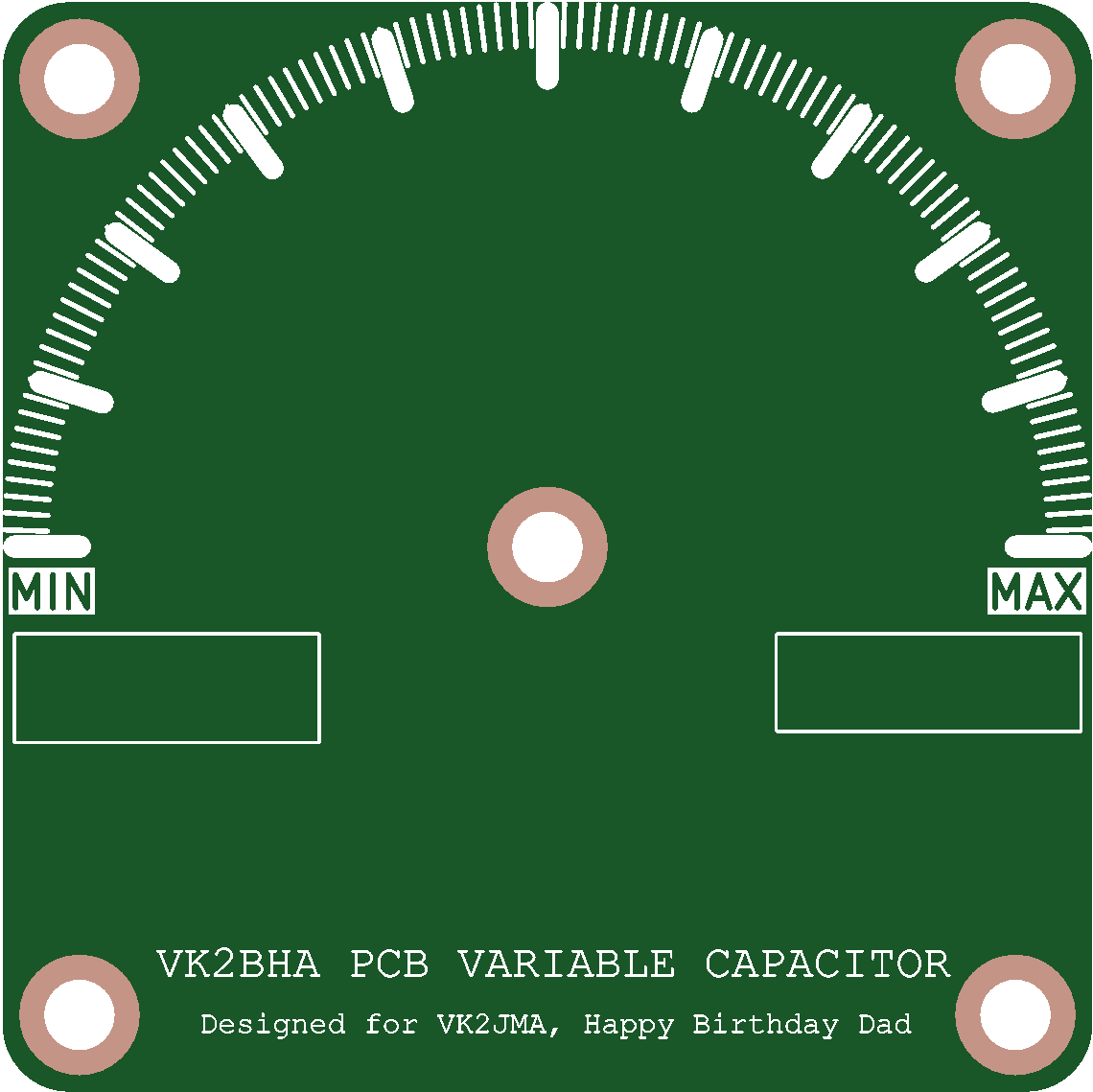
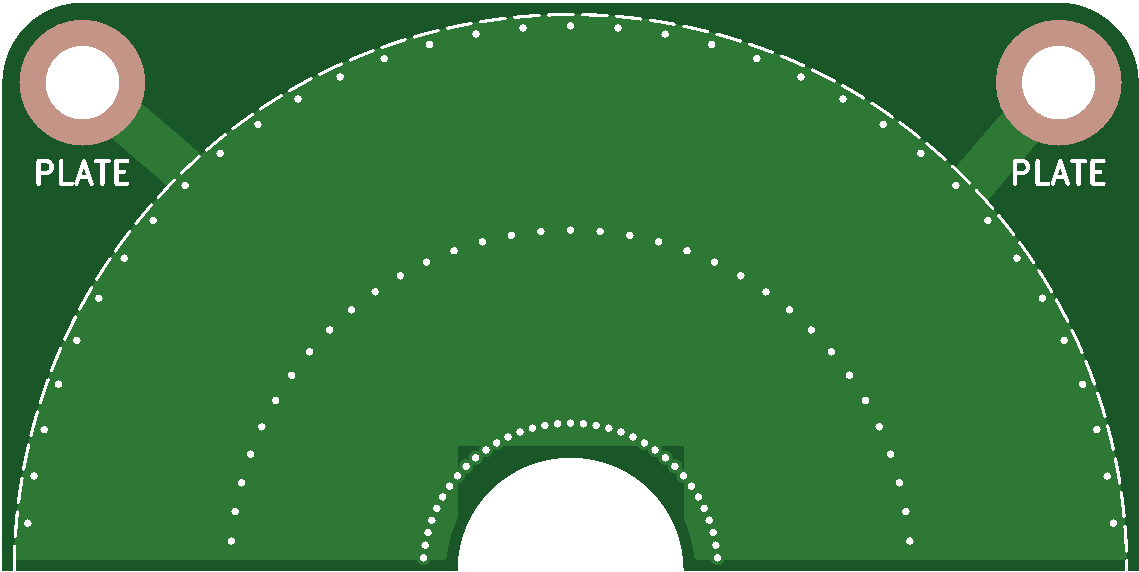
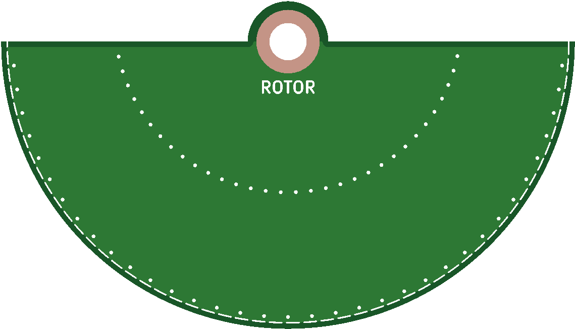

| Qty | Value | Footprint | References |
|---|---|---|---|
| 8 | MountingHole_3.2mm_M3_ISO14580_Pad_TopBottom | MountingHole:MountingHole_3.2mm_M3_ISO14580_Pad_TopBottom | PLATE, PLATE, PLATE, PLATE, ROTOR, ROTOR, ROTOR, ROTOR |
The 8 most common of 12 parts.
It measures 100 × 52 mm and has 2 copper layers, 1.6 mm thick.
12 parts. The full list of its parts is on this page, with links to each part's symbol and footprint where PCBKit's library has them.
From the pingu2211/pcb-variable-capacitor repository on GitHub, at the commit this page was made from: the board is pcb-variable-capacitor.kicad_pcb. PCBKit opens the board in the browser, with nothing to install.
Its repository publishes it under the MIT licence: you may reuse it on that licence's terms (keep the author's notice, and for a copyleft licence share your changes alike).
pingu2211/pcb-variable-capacitor
An Variable Capacitor Kit made of stacked PCB's

pingu2211/pcb-variable-capacitor
An Variable Capacitor Kit made of stacked PCB's

github-linguist/linguist
Language Savant. If your repository's language is being reported incorrectly, send us a pull request!


google/mozc-devices
Circuit diagrams and firmware source code for Gboard DIY keyboards


hackclub/OnBoard
💡 Join 1,000 teenagers and make your first PCB with a $100 grant!

VoronDesign/Voron-Tap
Tap is a nozzle-based z-probe for the V2 and Trident printer designs. The entire toolhead moves to trigger an optical switch. Tap offers many advantages:

stacksmashing/pico-tpmsniffer
A simple, very experimental TPM sniffer for LPC bus