2 layers53 × 30 mm
Watermeter zigbee
pifactory/watermeter
Design files for making inductive sensor for reading out smart water meters.
11 parts12CC-BY-4.0

 pifactory/watermeter12
Design files for making inductive sensor for reading out smart water meters.
Watermeter sensor is an open-source printed circuit board by pifactory, from the pifactory/watermeter repository on GitHub, published under the CC-BY-4.0 licence. It is a 2-layer board of 32.5 × 18 mm with 15 parts on 14 nets, routed with 89 tracks and 23 vias.
It is built around the LDC2112PW and AP7354-18W5. Its parts include 5 capacitors, 2 resistors, 2 ICs and 1 connector. It belongs with the sensors and measurement boards of this library.




Design files for making inductive sensor for reading out smart water meters.
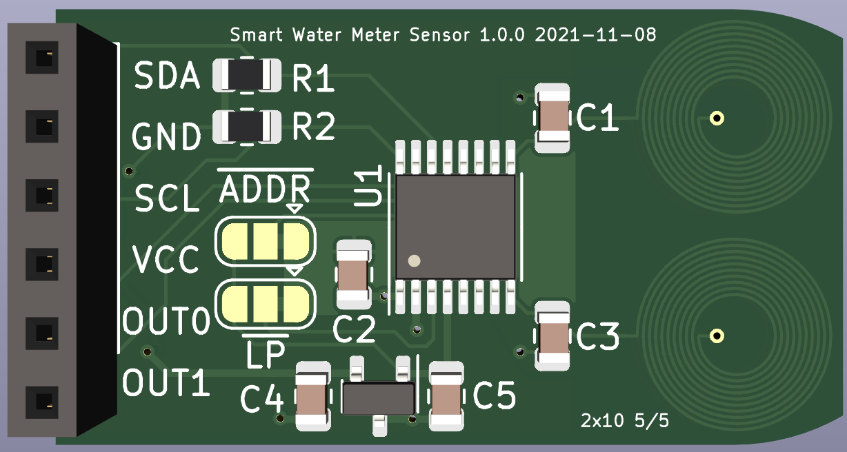
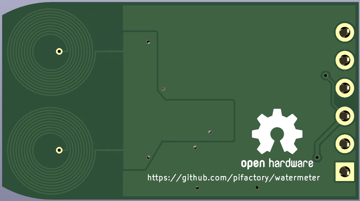
Many water meters are made 'smart-ready', ie they include a wheel under the glass which makes 1 turn per liter. Half of the wheel contains some metal (copper) on it which can be sensed by an inductive sensor.
Because of the costs water supply companies usually do not install smart reading device on such meters, but some nerds among us are stubborn enough to design and install their own reading device. Just to know how much water is used and be able to monitor it with, say, a Home Assistant. It can be also used to detect leaks.
One inductive sensor is not enough for reliable readings. There are some corner cases when the sensor will miss a turn of the wheel or count 1 turn 2 times. Think of it like this: wheel can stop at any moment at any angle and then continue movement at any time later on. During this stop environment can change significantly (temperature & humidity) to fool the sensing circuit. On top of it, to save power, each inductive sensor is scanned once in 800ms, ie there is no continous output from it. All in all, 2 inductive sensors allow to detect illogical readings and in many cases repair them.
For now here is just the sensor, controller is coming soon... I've made one for Zigbee already and it runs on 2 AAA batteries.
Here is the photo of the first prototype:
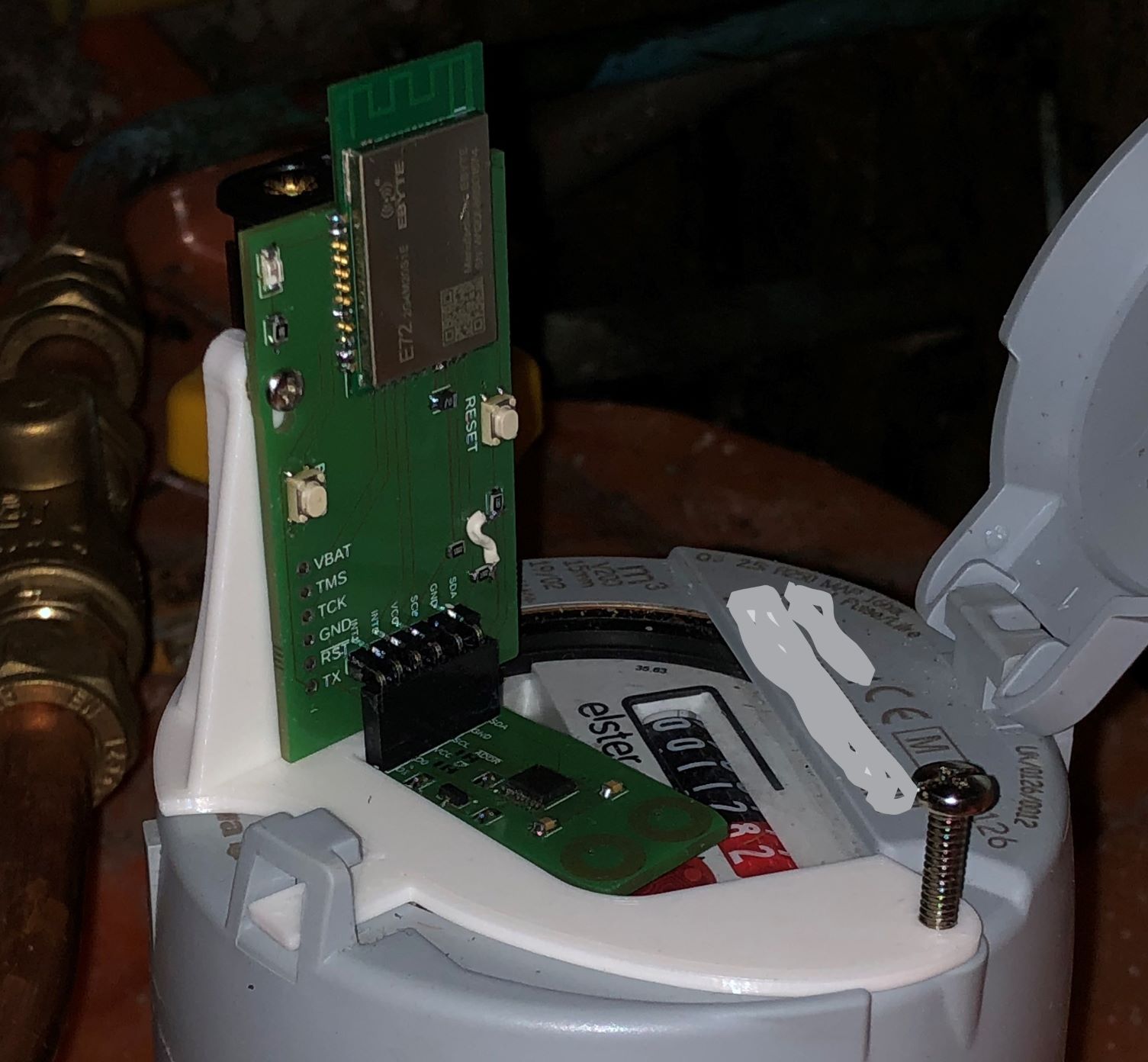
I used KiCAD 6 to make the design. You will probably also want to install kicad-goodies libraries, but this is not required.
A word about choosing a PCB shop. Inductive sensors on the PCB require as much as possible turns on as little space possible. This means that the traces have to be as thin as possible and the spacing between them has to be as small as possible. Also there is no copper around them + geometry of the traces = you might get shorts between traces if you push it to the limit.
Most shops out there (including JLCPCB) claim to be able to produce 6 mils traces with 6 mils spacing between them. I work with AISLER and they produce 5/5 mils boards for the same price, so this design has 5/5 PCB coils. I've made 6/6 PCB coils available in kicad-goodies, you can try them if 5/5 coils will not work for you. AISLER will need just *.kicad_pcb file, no Gerber is needed there and therefore not provided in this repo.
This repo has all you need to make a Zigbee microcontroller for the sensor:
Microcontroller is based on EBYTE module with CC2652P.
Firmware has following features:
Because of a bug in TI software, rejoin period cannot be longer than 5 minutes. Also rejoin uses more power than standard data report, so try to avoid situations when device stays on for longer periods without a connection to the network (like days, weeks, months)
Operation with 2 buttons and 1 LED:
Place provided pifactory_watermeter.js file in the same directory as configuration.yaml file.
Add these lines to configuration.yaml file:
external_converters:
    pifactory_watermeter.js
Restart Zigbee2MQTT and join the device
I've made a holder which fits my Elster water meter. Meter without sensor looks like this:
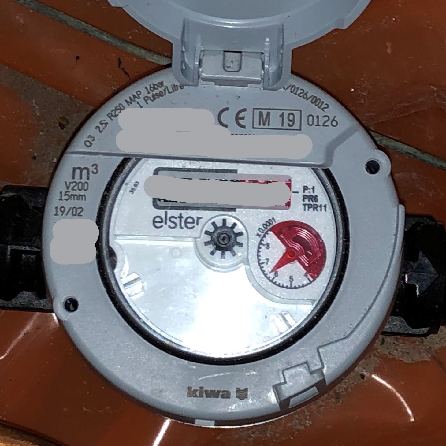
I didn't tried the holder on any other meter, but I suspect it fits different models as well. Please share your meters/holders or contact me if you need help fitting this sensor to your meter.
This work is licensed under a Creative Commons Attribution 4.0 International License.

| Qty | Value | Footprint | References |
|---|---|---|---|
| 2 | 1nF | Capacitor_SMD:C_0805_2012Metric | C1, C3 |
| 2 | 1uF | Capacitor_SMD:C_0603_1608Metric | C4, C5 |
| 2 | 30k | Resistor_SMD:R_0603_1608Metric | R1, R2 |
| 2 | PCB coil | pcb_coils:pcb_coil_8mm_2Lx10T_5-5 | PXI1, PXI2 |
| 1 | 10nF | Capacitor_SMD:C_0805_2012Metric | C2 |
| 1 | AP7354-18W5 | Package_TO_SOT_SMD:TSOT-23-5 | U2 |
| 1 | Conn_01x06 | Connector_PinSocket_2.54mm:PinSocket_1x06_P2.54mm_Vertical | J1 |
| 1 | LDC2112 | Package_SO:TSSOP-16_4.4x5mm_P0.65mm | U1 |
| 1 | ~{ADDR} | Jumper:SolderJumper-3_P1.3mm_Bridged12_RoundedPad1.0x1.5mm | JP1 |
| 1 | ~{LP} | Jumper:SolderJumper-3_P1.3mm_Bridged12_RoundedPad1.0x1.5mm | JP2 |
The 14 most common of 15 parts.
pifactory/watermeter
Design files for making inductive sensor for reading out smart water meters.

google/mozc-devices
Circuit diagrams and firmware source code for Gboard DIY keyboards

hoglet67/RGBtoHDMI
Bare-metal Raspberry Pi project that provides pixel-perfect sampling of Retro Computer RGB/YUV video and conversion to HDMI

mntmn/amiga2000-gfxcard
MNT VA2000, an Open Source Amiga 2/3/4000 Graphics Card (Zorro II/III), written in Verilog

hackclub/OnBoard
💡 Join 1,000 teenagers and make your first PCB with a $100 grant!

kenp-io/not-for-airpods-repairs
The content of this repository is licensed under the WTFPL License. Please have a close look at the terms before using this material.

Luos-io/luos_engine
Open-source and real-time orchestrator for cyber-physical-systems, to easily design, test and deploy embedded applications and digital twins.

Chrismettal/EleLab_v2
Cheap DIY lab system for hobbyists and the tinkering folk

It measures 32.5 × 18 mm and has 2 copper layers, 1.58 mm thick.
15 parts, built around the LDC2112PW and AP7354-18W5. The full list of its parts is on this page, with links to each part's symbol and footprint where PCBKit's library has them.
From the pifactory/watermeter repository on GitHub, at the commit this page was made from: the board is pcbs/watermeter_sensor/watermeter_sensor.kicad_pcb and its schematic pcbs/watermeter_sensor/watermeter_sensor.kicad_sch. PCBKit opens the board in the browser, with nothing to install.
Its repository publishes it under the CC-BY-4.0 licence: you may reuse it on that licence's terms (keep the author's notice, and for a copyleft licence share your changes alike).