2 layers25 × 25 mm
Bypass capacitor
pierre-bouckson/Chess_clock_using_STM32
A fully functional chess clock built with an STM32 microcontroller, using hardware timers and external components for a realistic, competitive experience.
4 parts1

 pierre-bouckson/Chess_clock_using_STM321
A fully functional chess clock built with an STM32 microcontroller, using hardware timers and external components for a realistic, competitive experience.
Hardware kicad is an open-source printed circuit board by pierre-bouckson, from the pierre-bouckson/Chess_clock_using_STM32 repository on GitHub. It is a 2-layer board with 36 parts on 33 nets, routed with 440 tracks and 32 vias.
It is built around the MAX6958AAEE+T and TDSG3160-M. Its parts include 22 resistors, 4 connectors and 2 ICs.


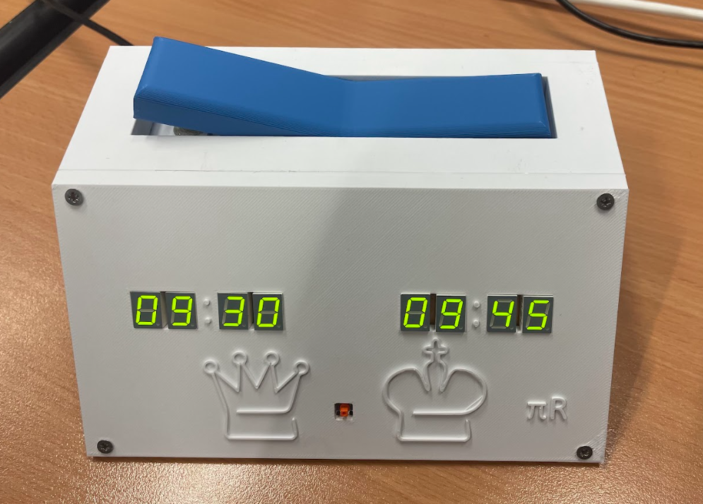
A fully functional chess clock built with an STM32 microcontroller, using hardware timers and external components for a realistic, competitive experience. This project combines embedded programming, electronics, and 3D printing.
The chess clock is powered by an STM32F072RB, using two hardware timers (TIM6 and TIM7) to track each player's countdown in real time. Turn switching is handled by a physical mechanism using a rotating shaft and magnets. Two MAX6958 drivers control the 7-segment displays. The clock supports multiple time modes and optional time increments.
Insert magnets into the 4 dedicated holes.
Create a custom push-button using aluminum (as shown below):
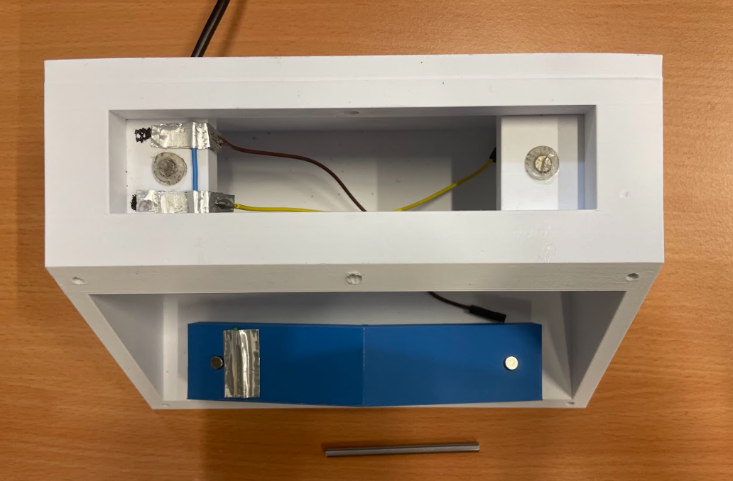
Connect the button between 5V and PB0.
Drill a hole in the enclosure to pass the power cable.
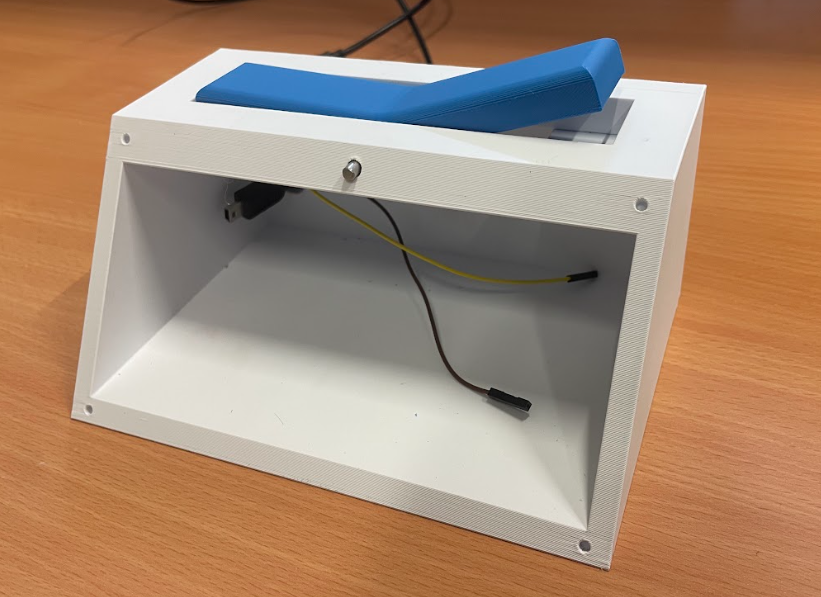
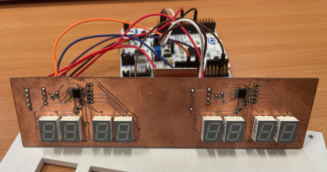
Use 4 pull-up resistors (1kΩ) for I2C communication.
Use 9 resistors (330Ω) for the LED segments.
Connect the first display driver to:
Connect the second driver to:
Don't forget to add decoupling capacitors near the power pins.
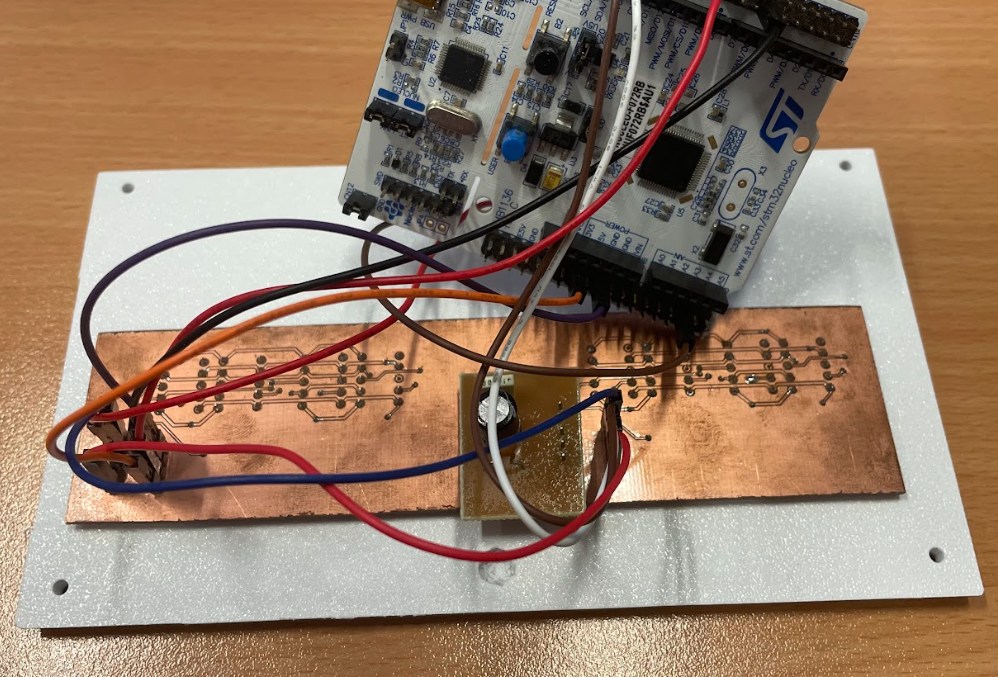
3D_model/ – 3D-printable enclosure files (STL)software_STM32/ – STM32 firmware (C)Image/ – Photoshardware_kicad/ – Schematics and PCB filesREADME.md – This fileFeel free to clone the repository, give feedback, or open issues!
| Qty | Value | Footprint | References |
|---|---|---|---|
| 22 | R | Resistor_SMD:R_0805_2012Metric | R1, R1, R2, R2, R3, R3, R4, R4, R5, R5, R6, R6, R10, R10, R11, R11 +6 |
| 8 | TDSG3160-M | footprints:DIP10_TDS | 1er1, 1er1, 2eme1, 2eme1, 3eme1, 3eme1, 4eme1, 4eme1 |
| 2 | Conn_01x04_Pin | Connector_PinHeader_2.54mm:PinHeader_1x04_P2.54mm_Vertical | J1, J1 |
| 2 | Conn_01x05_Pin | Connector_PinHeader_2.54mm:PinHeader_1x05_P2.54mm_Vertical | J2, J2 |
| 2 | max6958aaee | CMS:21-0055H_16_MXM | U2, U2 |
pierre-bouckson/Chess_clock_using_STM32
A fully functional chess clock built with an STM32 microcontroller, using hardware timers and external components for a realistic, competitive experience.

hoglet67/RGBtoHDMI
Bare-metal Raspberry Pi project that provides pixel-perfect sampling of Retro Computer RGB/YUV video and conversion to HDMI

hackclub/OnBoard
💡 Join 1,000 teenagers and make your first PCB with a $100 grant!


tardate/LittleArduinoProjects
a collection of "Little Electronic & Arduino Projects", most involving electronics or an Arduino in one way or another!


Neumi/open_echo
Open Source echo sounder / depth sounder / SONAR for bathymetry and research. Arduino based and compatible.


36 parts, built around the MAX6958AAEE+T and TDSG3160-M. The full list of its parts is on this page, with links to each part's symbol and footprint where PCBKit's library has them.
From the pierre-bouckson/Chess_clock_using_STM32 repository on GitHub, at the commit this page was made from: the board is hardware_kicad/hardware_kicad.kicad_pcb and its schematic hardware_kicad/bypass capacitor/bypass capacitor.kicad_sch. PCBKit opens the board in the browser, with nothing to install.
Its repository states no licence, so its author keeps all rights: ask pierre-bouckson before reusing the design.