
2 layers47 × 53.3 mm

 picuino/freqcounter1
Simple Frequency Counter with 8 digits of resolution.
Freqcounter 16F18446 is an open-source printed circuit board by picuino, from the picuino/freqcounter repository on GitHub. It is a 2-layer board of 91.4 × 41.9 mm with 45 parts on 41 nets, routed with 395 tracks and 39 vias.
It is built around the PIC16F15325-E/P, PIC16F18446-E/P and LM1117-3.3, with the 1N4148W among its other parts. Its parts include 14 resistors, 10 capacitors, 9 connectors, 3 ICs and 2 diodes. It belongs with the PIC boards of this library.


This is a cheap and simple but powerful frequency counter capable of measurements of frequency with 8 digits of resolution every second (9 digits of resolution in 10 second averages).
This frequency counter is based on a little PIC 16F18446 a 16x2 LCD display (optional) and USB-Serial interface with PC.
All the programs and hardware designs are free, open source and open hardware.
The frequency counter have a Command Line Interface via serial communications for manage multiple internal options. You can read more in Command Line Interface help
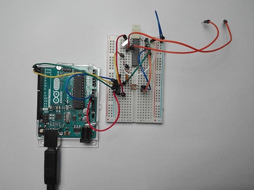
You can mount the frequency counter over a breadboard with this simple schematic with a cost of few dollars. The LDC display is optional. All the info is sended via serial.
Example of frequency meter conected to an Arduino. Arduino gives power and serial communications with PC.
Orange cables are the 2 TTL inputs.
Creative Commons Atribution-ShareAlike version 4, for hardware designs, texts, photograps, layouts, schematics, and similar.
GNU General Public License version 3, for microcontroller and computer programs.
| Qty | Value | Footprint | References |
|---|---|---|---|
| 6 | 180 | Resistor_SMD:R_0805_2012Metric_Pad1.15x1.40mm_HandSolder | R2, R3, R6, R7, R11, R12 |
| 4 | Footprints:SCREW_M3 | M3, M3, M3, M3 | |
| 3 | 100nF | Capacitor_SMD:C_0805_2012Metric_Pad1.15x1.40mm_HandSolder | C4, C5, C10 |
| 2 | 10K | Resistor_SMD:R_0805_2012Metric_Pad1.15x1.40mm_HandSolder | R4, R9 |
| 2 | 10uF | Capacitor_SMD:C_0805_2012Metric_Pad1.15x1.40mm_HandSolder | C7, C11 |
| 2 | 10uF | Capacitor_THT:C_Rect_L4.6mm_W5.5mm_P2.50mm_MKS02_FKP02 | C8, C9 |
| 2 | 1N4148W | Diode_SMD:D_SOD-123 | D1, D2 |
| 2 | 220 | Resistor_SMD:R_0805_2012Metric_Pad1.15x1.40mm_HandSolder | R8, R10 |
| 2 | 22pF | Capacitor_SMD:C_0805_2012Metric_Pad1.15x1.40mm_HandSolder | C2, C3 |
| 1 | 10M | Resistor_SMD:R_0805_2012Metric_Pad1.15x1.40mm_HandSolder | R13 |
| 1 | 10k | Resistor_SMD:R_0805_2012Metric_Pad1.15x1.40mm_HandSolder | R5 |
| 1 | 1K | Resistor_SMD:R_0805_2012Metric_Pad1.15x1.40mm_HandSolder | R1 |
| 1 | 2.2nF | Capacitor_SMD:C_0805_2012Metric_Pad1.15x1.40mm_HandSolder | C1 |
| 1 | 2K2 | Resistor_SMD:R_0805_2012Metric_Pad1.15x1.40mm_HandSolder | R14 |
| 1 | 8MHz | Crystal:Crystal_HC18-U_Vertical | Y1 |
| 1 | ICSP | Connector_PinHeader_2.54mm:PinHeader_1x05_P2.54mm_Vertical | J1 |
| 1 | ICSP2 | Connector_PinHeader_2.54mm:PinHeader_1x05_P2.54mm_Vertical | J8 |
| 1 | INPUT A | Connector_PinHeader_2.54mm:PinHeader_1x02_P2.54mm_Vertical | J4 |
| 1 | INPUT B | Connector_PinHeader_2.54mm:PinHeader_1x02_P2.54mm_Vertical | J5 |
| 1 | INPUT CLK | Connector_PinHeader_2.54mm:PinHeader_1x02_P2.54mm_Vertical | J3 |
| 1 | INPUT ZCD | Connector_PinHeader_2.54mm:PinHeader_1x02_P2.54mm_Vertical | J6 |
| 1 | Jumper | Connector_PinHeader_2.54mm:PinHeader_1x02_P2.54mm_Vertical | JP1 |
| 1 | LCD_DISPLAY_16X2 | Connector_PinHeader_2.54mm:PinHeader_1x16_P2.54mm_Vertical | P1 |
| 1 | LM1117 | Footprints:SOT223_LM1117 | U2 |
| 1 | NTC 10K | Resistor_SMD:R_0805_2012Metric_Pad1.15x1.40mm_HandSolder | TH1 |
| 1 | PIC16F15325 | Package_SO:SOIC-14_3.9x8.7mm_P1.27mm | U3 |
| 1 | PIC16F18446 | Package_SO:SOIC-20W_7.5x12.8mm_P1.27mm | U1 |
| 1 | POWER | Connector_PinHeader_2.54mm:PinHeader_1x02_P2.54mm_Vertical | J7 |
| 1 | UART | Connector_PinHeader_2.54mm:PinHeader_1x05_P2.54mm_Vertical | J2 |


dchwebb/MidiMonger
Eurorack MIDI interface supporting USB and serial MIDI. Based on ARM STM32F446 MCU.


daverowntree/SmartDesk
I open sourced a design I made a few years back for a non-paying client. Use it as you see fit!

PCBench/PCBench
resolution = [0.5, 0.5] pcbfolder = '../PCBs/' pcbnames = ["1Bitsy1bitsy"] iters = 30 env = PCBRoutingEnv(resolution=resolution, pcbfolder=pcbfolder, pcbnames=pcbnames) obs, info = env.reset() for in range(iters): act =…
It measures 91.4 × 41.9 mm and has 2 copper layers, 1.6 mm thick.
45 parts, built around the PIC16F15325-E/P, PIC16F18446-E/P, LM1117-3.3 and 1N4148W. The full list of its parts is on this page, with links to each part's symbol and footprint where PCBKit's library has them.
From the picuino/freqcounter repository on GitHub, at the commit this page was made from: the board is standalone_board/kicad/freqcounter_16F18446.kicad_pcb. PCBKit opens the board in the browser, with nothing to install.
Its repository states no licence, so its author keeps all rights: ask picuino before reusing the design.