Skip to the content
PCBKitNew board
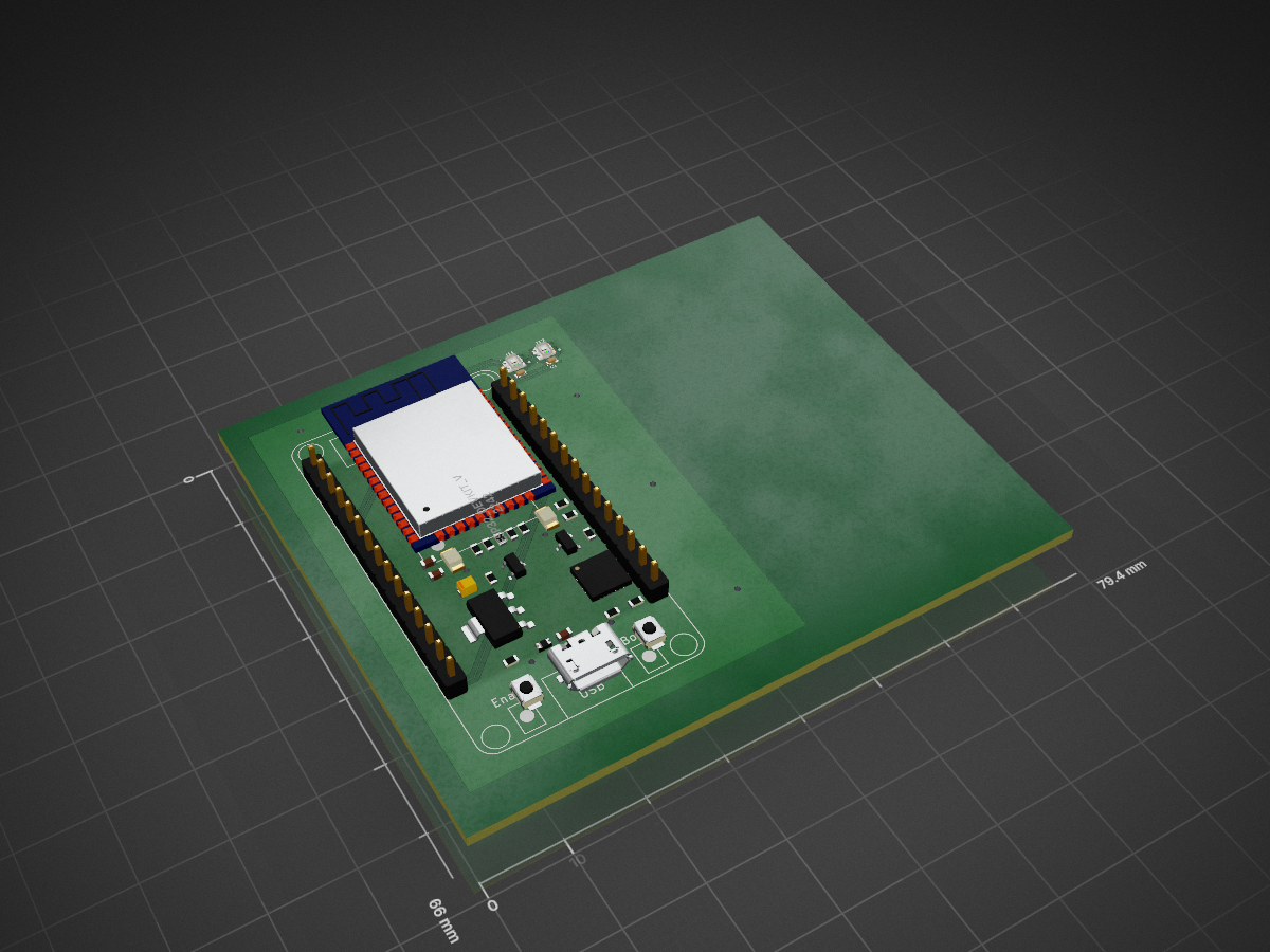
2 layers79.4 × 66 mmGithub display, the printed circuit board in 3D

An ESP32-powered LED matrix display that shows your GitHub contribution graph in real-time.

Size
79.4 × 66 mm
Copper layers
2
Thickness
1.6 mm
Parts
5
Nets
31
Pads
42
Tracks, vias
33, 10
Pours
1
Routed
Yes
KiCad
KiCad 9.0 (file 20241229)
Created
15 Oct 2025
Updated
23 Nov 2025

Overview

Github display is an open-source printed circuit board by phultquist, from the phultquist/github-display repository on GitHub. It is a 2-layer board of 79.4 × 66 mm with 5 parts on 31 nets, routed with 33 tracks and 10 vias.

It is built around the 0402YA470JAT2A. Its parts include 3 ICs and 2 capacitors. It belongs with the lEDs and displays boards and the ESP32 boards of this library.

Main components

1

README

README.md

GitHub Display

An ESP32-powered LED matrix display that shows your GitHub contribution graph in real-time.

Features

  • 256 LED (16x16) matrix display
  • Automatic WiFi connection with captive portal setup
  • Fetches data from custom API every 10 seconds
  • Hard-coded Device ID: "1"
  • WiFi credential reset functionality

Initial Setup

First Time Power-On

  1. Power on the device - The ESP32 will boot up
  2. Wait 3 seconds - The device will attempt to connect to WiFi (will fail on first boot)
  3. Connect to AP - A WiFi access point named GithubDisplay-Setup will appear
  4. Join the network - Connect your phone/computer to GithubDisplay-Setup
  5. Configure WiFi - A captive portal should open automatically (if not, navigate to 192.168.4.1)
  6. Enter credentials - Select your WiFi network and enter the password
  7. Save - Click "Save" and the device will connect to your WiFi
  8. Display starts - The LED matrix will begin displaying your GitHub data

What Happens Next

  • WiFi credentials are saved automatically in the ESP32's flash memory
  • On every subsequent boot, the device will auto-connect to your WiFi
  • The display updates every 10 seconds with fresh data from the API

Resetting WiFi Credentials

If you need to connect to a different WiFi network or clear the stored credentials:

Reset Procedure

  1. Press the RESET button (don't hold any other buttons)
  2. Watch the Serial Monitor - You'll see: 💡 Press and hold BOOT button now to clear WiFi (3 sec window)...
  3. Quickly press and hold BOOT - You have 3 seconds to press the BOOT button
  4. Keep holding for 2 seconds - The status LED will blink rapidly to show progress
  5. Wait for confirmation - After 2 seconds, you'll see 3 slow blinks = WiFi cleared!
  6. Device restarts in AP mode - The GithubDisplay-Setup AP will appear again
  7. Repeat initial setup - Follow the "First Time Power-On" steps above

Visual Feedback

  • Rapid blinking (during 2-second hold) = Counting down
  • 3 slow blinks = WiFi credentials successfully cleared
  • Solid LED = Device connected and running normally

Troubleshooting

Device stuck in download mode (red light only)

If you accidentally held BOOT while pressing RESET, the device enters bootloader mode:

Solution: Simply press the RESET button once (without holding BOOT) to recover

WiFi not connecting

  1. Check that your WiFi credentials are correct
  2. Make sure your WiFi network is 2.4GHz (ESP32 doesn't support 5GHz)
  3. Try resetting WiFi credentials and setting up again

Display not updating

  1. Check Serial Monitor for error messages
  2. Verify the device has internet access
  3. Confirm the API endpoint is accessible: https://github-display-server.vercel.app/api/1

Serial Monitor shows JSON parse errors

The API might be returning invalid data - check the API endpoint directly in a browser

Hardware

  • ESP32 Development Board
  • LED Strip: 256 LEDs (WS2812B/NeoPixel compatible) on GPIO 5
  • Status LED: GPIO 2 (built-in on most ESP32 boards)
  • BOOT Button: GPIO 0 (built-in on most ESP32 boards)
  • RESET Button: EN pin (built-in on most ESP32 boards)

API Endpoint

The device fetches data from:

text
https://github-display-server.vercel.app/api/1

Expected JSON format:

json
{
  "data": [
    [0, 255, 128, ...],  // Row 1: 16 values (0-255)
    [0, 0, 255, ...],    // Row 2: 16 values (0-255)
    // ... 16 rows total
  ]
}

Each value represents the green intensity (0-255) for that LED.

Development

Arduino IDE Setup

  1. Install the Arduino IDE
  2. Install ESP32 board support
  3. Install required libraries:
    • Adafruit NeoPixel
    • ArduinoJson
    • WiFiManager

Uploading Code

  1. Connect ESP32 via USB
  2. Select your board and port in Arduino IDE
  3. Click Upload
  4. Wait for compilation and upload to complete

Configuration

All configuration is at the top of sketch_oct14a.ino:

cpp
const char *API_BASE = "https://github-display-server.vercel.app/api";
const String DEVICE_ID = "1";
const int NUM_LEDS = 256;
const int STRIP_BRIGHTNESS = 5;

Adjust STRIP_BRIGHTNESS (0-255) if the display is too bright or too dim.

Parts

5
QtyValueFootprintReferences
20402YA470JAT2A0402YA470JAT2A:CAPC1005X56NC1, C2
2WS2812-2020WS2812-2020:LED_WS2812-2020U1, U2
1ESP32_DevKit_V1_DOITesp32_kicad_mod:esp32_devkit_v1_doitU3

Questions

How big is the Github display PCB?

It measures 79.4 × 66 mm and has 2 copper layers, 1.6 mm thick.

What parts does the Github display use?

5 parts, built around the 0402YA470JAT2A. The full list of its parts is on this page, with links to each part's symbol and footprint where PCBKit's library has them.

Where can I download the Github display KiCad files?

From the phultquist/github-display repository on GitHub, at the commit this page was made from: the board is pcb/pcb/pcb.kicad_pcb and its schematic github-display/github-display.kicad_sch. PCBKit opens the board in the browser, with nothing to install.

Can I use the Github display design in my own project?

Its repository states no licence, so its author keeps all rights: ask phultquist before reusing the design.

Similar boards

  • 2 layers98 × 27 mmXy limit, the printed circuit board in 3D

    Xy limit

    opulo-inc/lumenpnp

    The LumenPnP is an open source pick and place machine.

    5 parts3.7k
  • 2 layers21 × 33 mm24g2usb pico2w, the printed circuit board in 3D

    24g2usb pico2w

    joypad-ai/joypad-os

    Universal controller firmware for building adapters, dongles, and custom controllers.

    5 parts1.7kApache-2.0
  • 2 layers53.2 × 59.6 mmA10 OLinuXino Lime Rev B SHIELD TEMPLATE, the printed circuit board in 3D

    A10 OLinuXino Lime Rev B SHIELD TEMPLATE

    OLIMEX/OLINUXINO

    OLINUXINO is Open Source / Open Hardware, low cost from EUR 24 Linux Industrial grade Single Board Computer capable to operate -25+85C

    5 parts1.5k
  • 2 layers30 × 11 mmMain control board servo tester, the printed circuit board in 3D

    Main control board servo tester

    jamro/tiny-engineer

    A small desktop robot that brings an AI coding assistant to life, physically acting out when it reads files, thinks, writes code, and finishes work.

    5 parts1.1k
  • 2 layers78.8 × 35.3 mmKiCadTest, the printed circuit board in 3D

    KiCadTest

    hackclub/OnBoard

    💡 Join 1,000 teenagers and make your first PCB with a $100 grant!

    5 parts915
  • 2 layers50 × 23 mmMiniCircuits LTCC, the printed circuit board in 3D

    MiniCircuits LTCC

    VanceVagell/kv4p-ht

    Open source handheld ham radio project KV4P-HT

    5 parts828GPL-3.0
  • 2 layers20.3 × 15.2 mmL0 light sensor, the printed circuit board in 3D

    L0 light sensor

    Luos-io/luos_engine

    Open-source and real-time orchestrator for cyber-physical-systems, to easily design, test and deploy embedded applications and digital twins.

    5 parts546MIT