2 layers40 × 68 mm
MULTIGW
nuclearcat/ESP32ETH
Simple ESP32 with native ethernet using LAN8720 phy, Arduino compatible
32 parts30LGPL-2.1

 PhilipHiet/ESP32-RTL8201F-devboard
Develpoment-board for the ESP32 with a RTL8201F ethernet transceiver and an onboard USB-C debug-interface
ESP32-RTL8201F devboard is an open-source printed circuit board by PhilipHiet, from the PhilipHiet/ESP32-RTL8201F-devboard repository on GitHub, published under the MIT licence. It is a 4-layer board of 33 × 68.5 mm with 52 parts on 84 nets, routed with 551 tracks and 90 vias.
It is built around the CH340C, ESP32-WROOM-32 and AMS1117-3.3, with the SS14, SS8050 and HR911105A among its other parts. Its parts include 25 resistors, 13 capacitors, 4 ICs, 4 connectors and 3 diodes. It belongs with the microcontroller boards and interfaces and adapters boards and the ESP32 boards of this library.


A simple ESP32 devboard with WiFi and Ethernet using the RTL8201F transceiver including an onboard USB-C-port for power, programming and serial console.
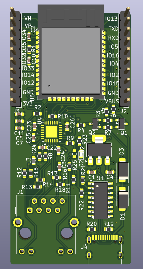
The schematics are based on the esp-32-poe-dev project by @jorticus but using the ESP32-WROOM-32E module instead of a barebone ESP32.
This board is designed as a 4-layer PCB and is optimized for cheap assembly with JLCPCB. So using basic parts where possible and a custom ESP32-WROOM-32E footrpint so the minimum via-hole-size is 0.3mm.
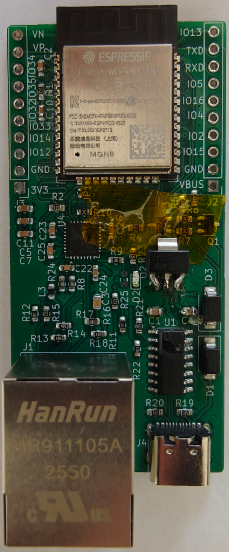
The boards were fully assembled by JLCPCB (except for the pinheaders). The necessary production files are included under pcb/jilcpcb.
In the first interation I chose the wrong 3.3V LDO and had to amnually swap those. The uploaded board- and assembly-files are already fixed.
Save the esp32-rtl8201f-devboard.json into the boards directory of your platform.io project. Creating the folder if it doesn't exist yet.
Select the board in your platformio.ini
[env:esp32dev]
monitor_speed=115200
platform = espressif32
board = esp32-rtl8201f-devboard
framework = arduino
Now you can #include <ETH.h> and call ETH.begin(); in your code.
Check out the firmware-examples for more details.
The main goal was to have a more stable link than the onboard wifi and with packet-loss around .00003% in my test I think it's pretty stable.
Enabling WiFi or Bluetooth while Ethernet is running can make the Ethernet link unstable on this board. A working workaround is to force the RTL8201F PHY to 10 Mbit/s; once the wireless radios are disabled again, auto-negotiation can be restored to use 100 Mbit/s.
The snippets below use the Arduino-ESP32 3.2+ API. Older cores (including the 2.x core still used by some PlatformIO espressif32 releases) do not expose ETH.setLinkSpeed() or ETH.setAutoNegotiation(); use Arduino-ESP32 3.2+ or an ESP-IDF 5.x project if you need this workaround.
Force 10 Mbit/s before starting Ethernet:
#include <ETH.h>

void ethernetBegin10Mbit() {
  ETH.setAutoNegotiation(false);  // required before changing the speed
  ETH.setLinkSpeed(10);           // 10 Mbit/s, full duplex
  ETH.begin();
}
Restore auto-negotiation at runtime, for example after turning WiFi/Bluetooth off. This restarts the interface, so expect a short link drop and IP reconfiguration:
void ethernetUseAutoSpeed() {
  ETH.end();
  ETH.setAutoNegotiation(true);
  ETH.begin();
}
To drop back to 10 Mbit/s later, restart the interface the same way:
void ethernetUse10Mbit() {
  ETH.end();
  ETH.setAutoNegotiation(false);
  ETH.setLinkSpeed(10);
  ETH.begin();
}| Qty | Value | Footprint | References |
|---|---|---|---|
| 9 | 10k | Resistor_SMD:R_0603_1608Metric | R1, R5, R6, R7, R9, R10, R11, R12, R25 |
| 7 | 100n | Capacitor_SMD:C_0603_1608Metric | C2, C7, C22, C23, C24, C25, C26 |
| 4 | 5k1 | Resistor_SMD:R_0603_1608Metric | R19, R20, R21, R22 |
| 3 | 49.9R 1% | Resistor_SMD:R_0603_1608Metric | R14, R17, R18 |
| 2 | 100 | Resistor_SMD:R_0603_1608Metric | R3, R4 |
| 2 | 1u | Capacitor_SMD:C_0603_1608Metric | C10, C11 |
| 2 | 22u | Capacitor_SMD:C_0603_1608Metric | C1, C4 |
| 2 | 270R | Resistor_SMD:R_0603_1608Metric | R15, R16 |
| 2 | 49R9 | Resistor_SMD:R_0603_1608Metric | R2, R13 |
| 2 | 4k99 1% | Resistor_SMD:R_0603_1608Metric | R8, R24 |
| 2 | Conn_01x10 | Connector_PinHeader_2.54mm:PinHeader_1x10_P2.54mm_Vertical | J2, J3 |
| 2 | SS14 | Diode_SMD:D_SMA | D1, D3 |
| 2 | SS8050 | Package_TO_SOT_SMD:SOT-23 | Q1, Q2 |
| 1 | 100n 100V | Capacitor_SMD:C_0603_1608Metric | C3 |
| 1 | 10u | Capacitor_SMD:C_0603_1608Metric | C5 |
| 1 | 470 | Resistor_SMD:R_0603_1608Metric | R23 |
| 1 | AMS1117-3.3 | Package_TO_SOT_SMD:SOT-223-3_TabPin2 | U2 |
| 1 | CH340C | Package_SO:SOIC-16_3.9x9.9mm_P1.27mm | U1 |
| 1 | ESP32-WROOM-32 | ESP32-RLT8201-devboard:ESP32-WROOM-32E | U6 |
| 1 | FB 600R@100MHz 1.3A | Inductor_SMD:L_0603_1608Metric | L3 |
| 1 | HR911105A | Connector_RJ:RJ45_Hanrun_HR911105A_Horizontal | J1 |
| 1 | LED | LED_SMD:LED_0603_1608Metric | D2 |
| 1 | RTL8201F | Package_DFN_QFN:QFN-32-1EP_5x5mm_P0.5mm_EP3.1x3.1mm | U4 |
| 1 | USB_C_Receptacle_USB2.0_16P | Connector_USB:USB_C_Receptacle_G-Switch_GT-USB-7010ASV | J4 |
It measures 33 × 68.5 mm and has 4 copper layers, 1.56 mm thick.
52 parts, built around the CH340C, ESP32-WROOM-32, AMS1117-3.3 and SS14. The full list of its parts is on this page, with links to each part's symbol and footprint where PCBKit's library has them.
From the PhilipHiet/ESP32-RTL8201F-devboard repository on GitHub, at the commit this page was made from: the board is pcb/ESP32-RTL8201F-devboard.kicad_pcb and its schematic pcb/ESP32-RTL8201F-devboard.kicad_sch. PCBKit opens the board in the browser, with nothing to install.
Its repository publishes it under the MIT licence: you may reuse it on that licence's terms (keep the author's notice, and for a copyleft licence share your changes alike).
nuclearcat/ESP32ETH
Simple ESP32 with native ethernet using LAN8720 phy, Arduino compatible

ampnics/CAN-to-WiFi-Converter-Dongle-
CAN to WiFi Converter PCB using ESP32! This step-by-step tutorial covers schematic creation, PCB layout, and best practices for signal integrity. Perfect for automotive and IoT applications!

moksh-pcb-design/ESP32-WROOM-Development-Board
Custom ESP32-WROOM-32 Development Board designed in KiCad 10 featuring USB Type-C, CH340C USB-UART interface, AMS1117 power regulation and auto-programming circuitry.

7205jmj/Custom-ESP32-WROOM-32-Development-Board
Most ESP32 development boards available in the market include additional features that may not be required for every project.


Adichidrawar/electronics-assessment-IF
Hardware design solution for the Intelligence Factory Hardware/Mechatronics Engineer take-home assessment. Includes a two-board ESP32-based embedded system with a remote IMU sensor board, complete PCB design in KiCad…

arm-n/ESP-WROOM-32-Development-Board
A hardware prototyping project based on the ESP-WROOM-32 module, designed using KiCad. This repository contains the circuit schematic, PCB layout, Gerber manufacturing files, design screenshots, datasheets and…