appnote-amplifier
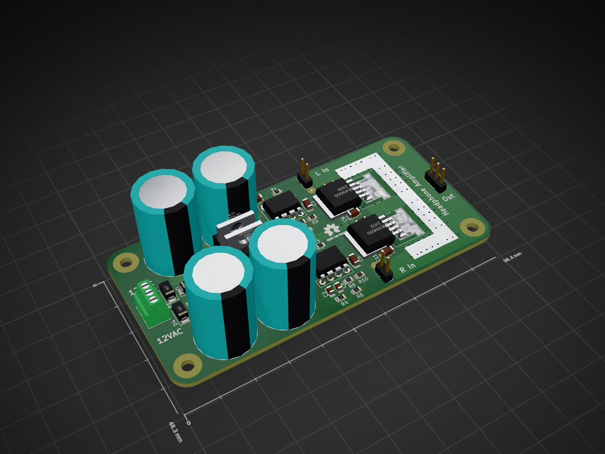
This is a PCB design for a headphone amplifier based on the example schematic in the LME49600 datasheet.
Power Supply
You will need a 12VAC or 24VAC centre-tapped transformer. The simplest/safest option is to use it with
a Class-II (double insulated) accredited 12VAC 0.5A plugpack and not ground any part of this design.
Use Phoenix-style screw terminals.
Inputs & Outputs
Place a 10K dual-gang A-scale volume pot between the signal source and the inputs to this board. Use 0.1"-pitch
Phoenix-style screw terminals.
Thermal
There is a bare patch on the board surrounding the output stage; you can solder a strip of copper
sheet here to act as a heatsink, if that seems to be necessary (almost certainly not). Note that it will be connected to the negative
rail, so don't let the heatsink touch anything.
Errata
Rev.A is missing reverse-protection diodes around the regulators. They are considered best-practise
for cases where the input voltage on a regulator may collapse faster than its output and as such should not be necessary for this design - the regulators should be the only current
drain upon the rectifier capacitors. They have been added to Rev.B on the basis of paranoia and can be hand-soldered onto the underside of a Rev.A board.
The BOM lists 7812 and 7912 regulators and 12VAC supply, which is more voltage than most headphones require. For headphones of no more than 64 ohms,
a 7805 and 7905 are enough and will need only a 6VAC transformer.
License
This hardware design is (C) 2017 William Brodie-Tyrrell and is licensed under the CERN OHL; see cern_ohl_v_1_2.pdf