2 layers40 × 20 mm

 pfroud/jeopardy-buzzer-controller
Buzzers for Jeopardy trivia game
Jeopardy buzzer controller is an open-source printed circuit board by pfroud, from the pfroud/jeopardy-buzzer-controller repository on GitHub. It is a 2-layer board of 250 × 46 mm with 13 parts on 40 nets, routed with 77 tracks and 0 vias.
Its parts include 3 connectors, 1 IC and 1 switch.
Pictures of the PCB:
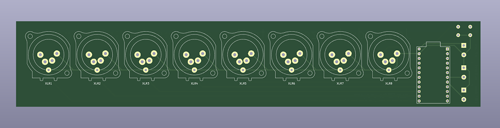 | 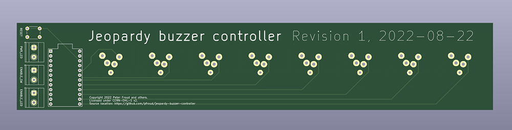 |
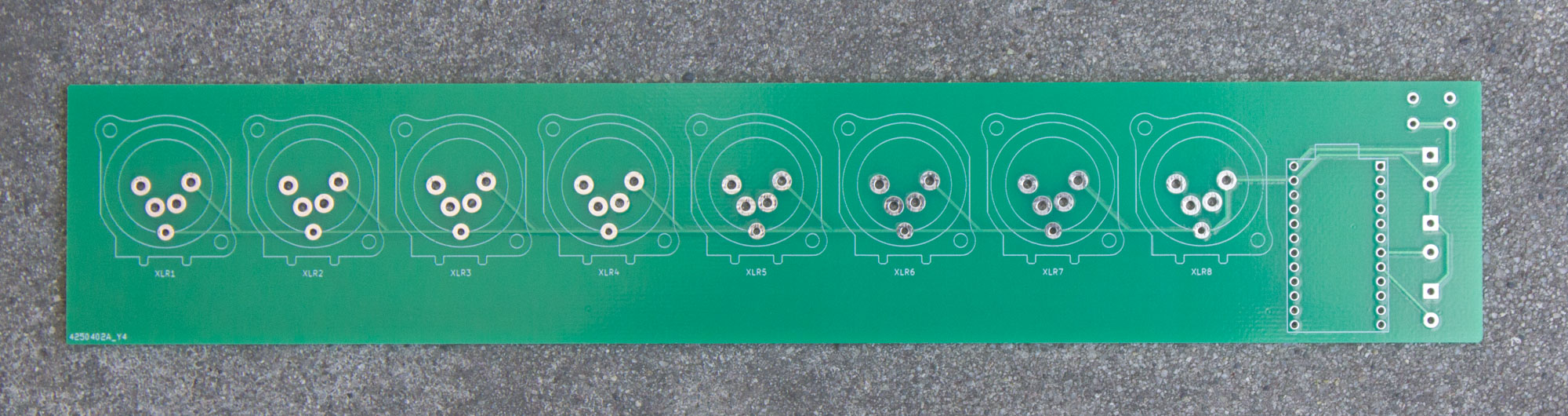 | 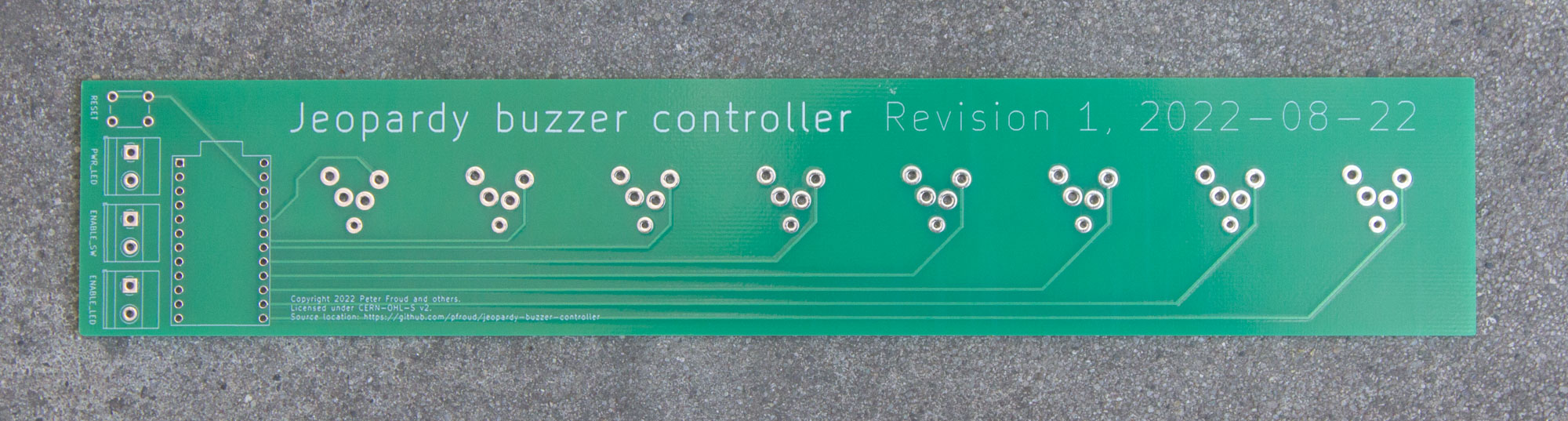 |
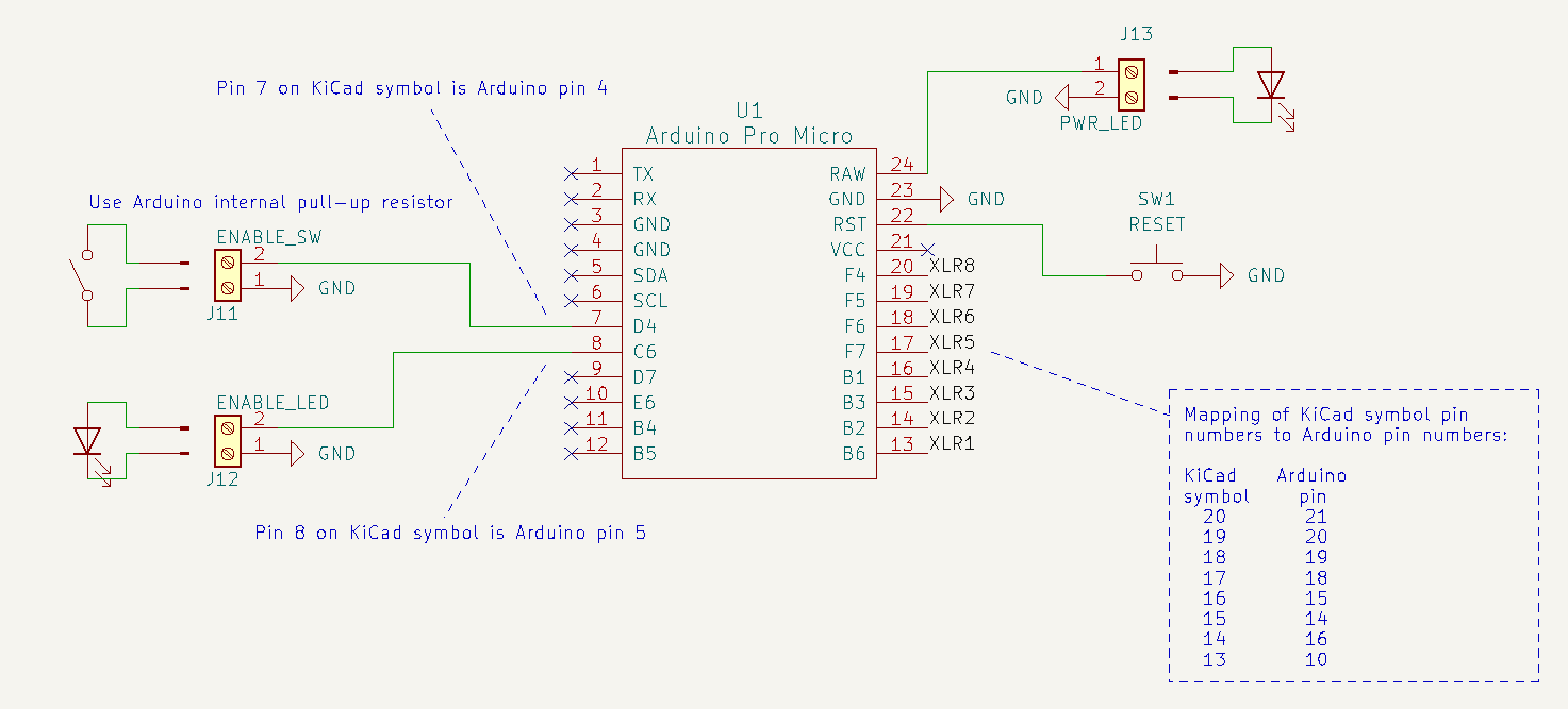
Only eight buzzers are supported and the Arduino has twelve digital I/O pins, so no matrix circuit is needed.
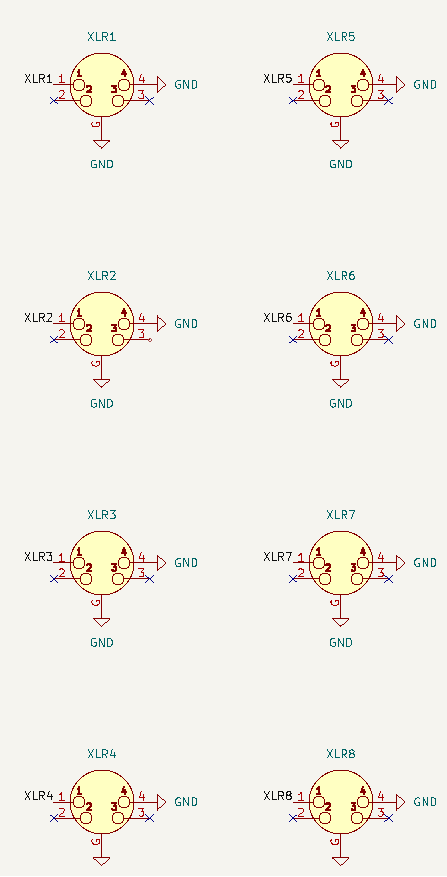
Here are screenshots of the schematic so you don't need to download / install / launch KiCad:
 |  |
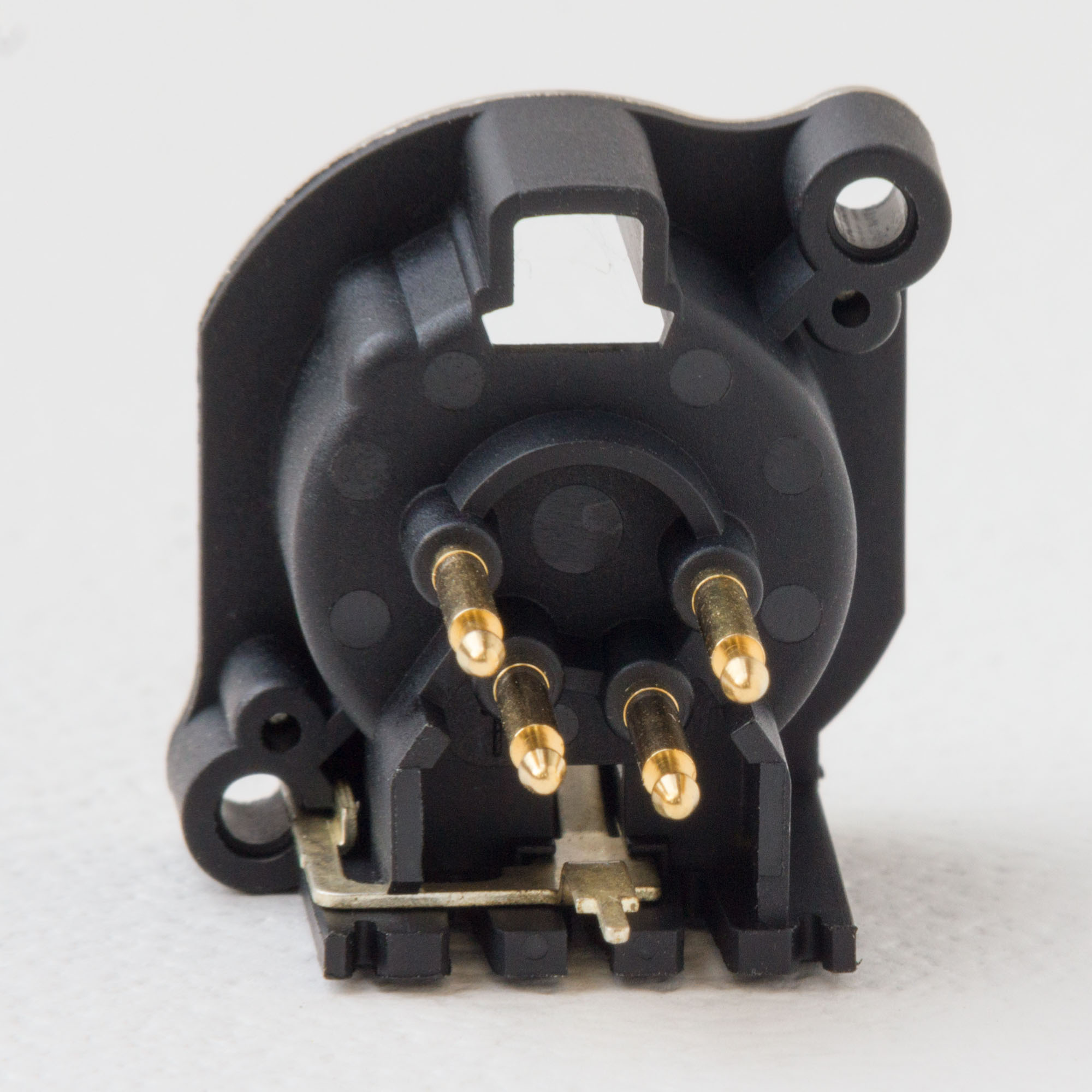
They are Neutrik NC4MBV which are:
4 pole male XLR receptacle, grounding: separate ground contact to mating connector shell and front panel.
Each connector has four cylindrical pins with shoulders. A rectangular tab on the bottom contacts the shell of the mating connector.
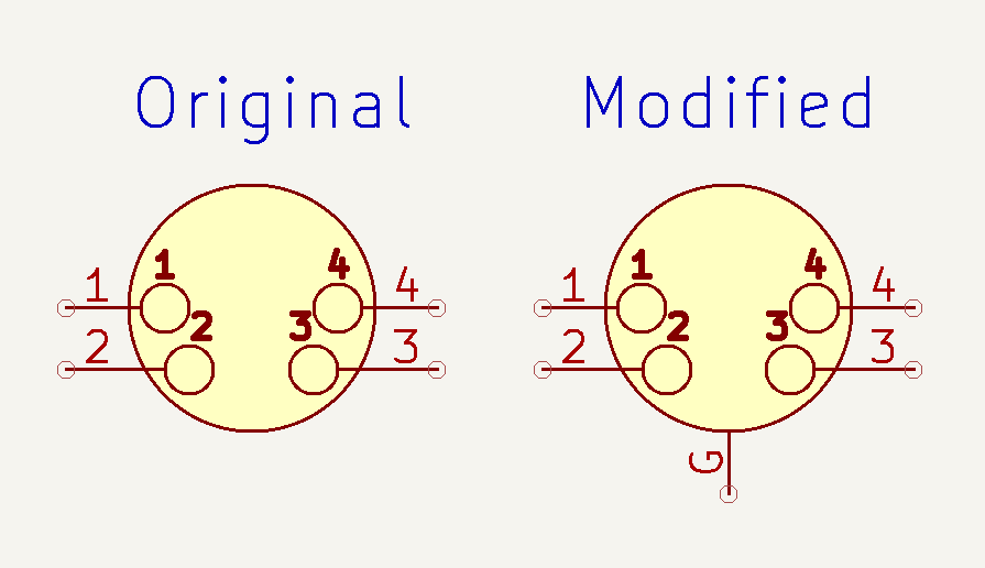
KiCad comes with symbols & footprints for 4-pin XLR connectors; I modified both slightly.
I added a ground pin to the "XLR4" symbol in the KiCad Connector library:
I started with the "Jack_XLR_Neutrik_NC4MBV_Vertical" footprint in the KiCad Connector_Audio library, which exactly matches the footprint provided by Neutrik.
After the PCB was fabricated, I saw that those dimensions hold the connector about ¼ inch (6 mm) above the board. The shoulders of the cylindrical pins and the square section of the ground tab both rest on the PCB surface. I think this looks sort of silly and expected the black plastic housing to touch the board.
To see a comparison, I drilled out the pads on an extra board. In the pictures below, the original footprint is on the left and the footprint with drilled-out holes is on the right:
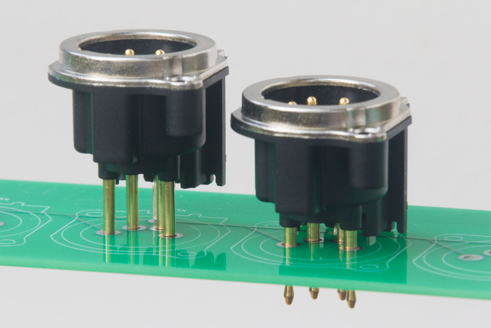 | 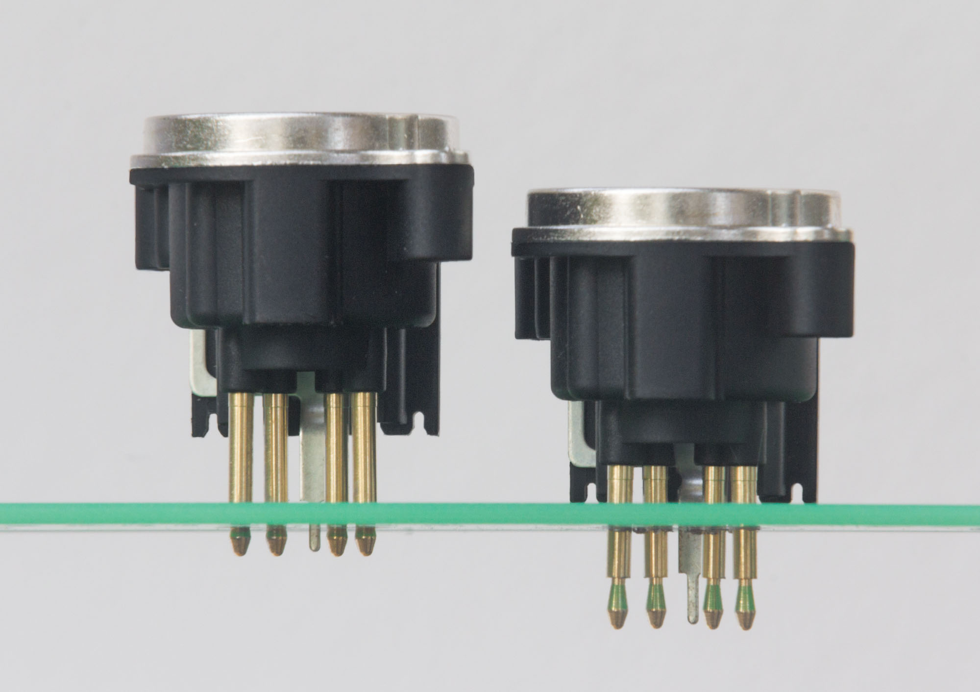 |
I edited the footprint to make the black plastic housing touch the PCB. First I increased the sizes of pads 1-4 so the full diameter of the cylinder could go through the board. Then I changed the ground pin from a circle to a slot to let the bigger non-square part of the ground tab go through as well.
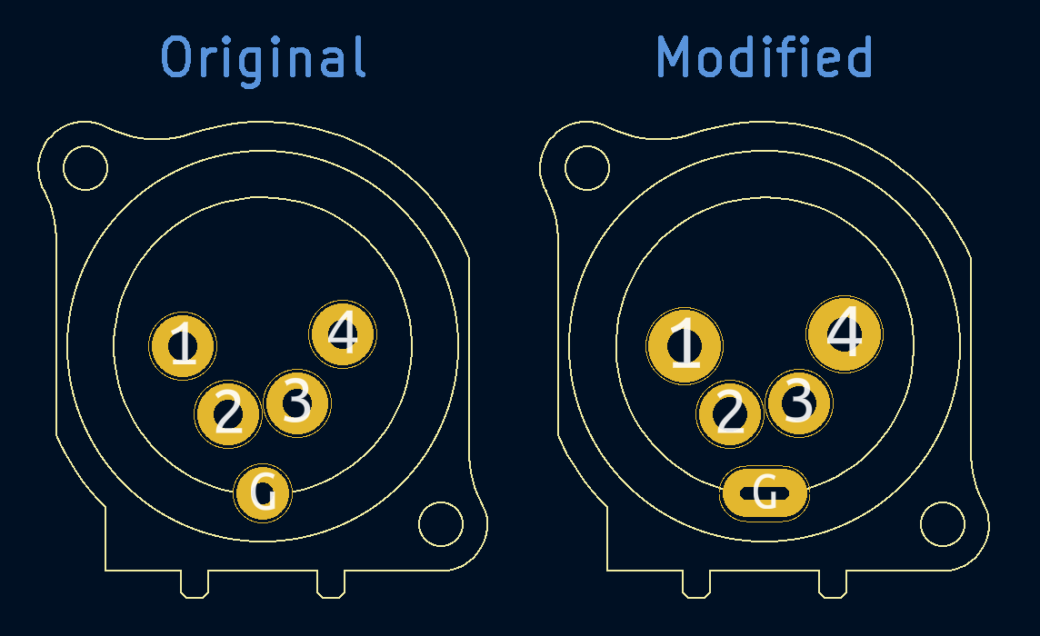
But I never got a board fabricated with the modified footprint! When assembling the PCB into the enclosure, I discovered that having the connectors on long legs was actually very helpful because they could bend slightly to accommodate imperfect hole alignment in the plastic wall.
| Qty | Value | Footprint | References |
|---|---|---|---|
| 1 | Arduino Pro Micro | Arduino_Pro_Micro:ProMicro | U1 |
| 1 | ENABLE_LED | TerminalBlock_Phoenix:TerminalBlock_Phoenix_MKDS-1,5-2-5.08_1x02_P5.08mm_Horizontal | J12 |
| 1 | ENABLE_SW | TerminalBlock_Phoenix:TerminalBlock_Phoenix_MKDS-1,5-2-5.08_1x02_P5.08mm_Horizontal | J11 |
| 1 | PWR_LED | TerminalBlock_Phoenix:TerminalBlock_Phoenix_MKDS-1,5-2-5.08_1x02_P5.08mm_Horizontal | J13 |
| 1 | RESET | Button_Switch_THT:SW_PUSH_6mm | SW1 |
| 1 | XLR1 | custom_xlr_footprint:Jack_XLR_Neutrik_NC4MBV_Vertical_with_bigger_holes | XLR1 |
| 1 | XLR2 | custom_xlr_footprint:Jack_XLR_Neutrik_NC4MBV_Vertical_with_bigger_holes | XLR2 |
| 1 | XLR3 | custom_xlr_footprint:Jack_XLR_Neutrik_NC4MBV_Vertical_with_bigger_holes | XLR3 |
| 1 | XLR4 | custom_xlr_footprint:Jack_XLR_Neutrik_NC4MBV_Vertical_with_bigger_holes | XLR4 |
| 1 | XLR5 | custom_xlr_footprint:Jack_XLR_Neutrik_NC4MBV_Vertical_with_bigger_holes | XLR5 |
| 1 | XLR6 | custom_xlr_footprint:Jack_XLR_Neutrik_NC4MBV_Vertical_with_bigger_holes | XLR6 |
| 1 | XLR7 | custom_xlr_footprint:Jack_XLR_Neutrik_NC4MBV_Vertical_with_bigger_holes | XLR7 |
| 1 | XLR8 | custom_xlr_footprint:Jack_XLR_Neutrik_NC4MBV_Vertical_with_bigger_holes | XLR8 |
It measures 250 × 46 mm and has 2 copper layers, 1.6 mm thick.
13 parts. The full list of its parts is on this page, with links to each part's symbol and footprint where PCBKit's library has them.
From the pfroud/jeopardy-buzzer-controller repository on GitHub, at the commit this page was made from: the board is KiCad_project/jeopardy_buzzer_controller.kicad_pcb and its schematic KiCad_project/jeopardy_buzzer_controller.kicad_sch. PCBKit opens the board in the browser, with nothing to install.
Its repository states no licence, so its author keeps all rights: ask pfroud before reusing the design.


samyk/magspoof
A portable device that can spoof/emulate any magnetic stripe, credit card or hotel card "wirelessly", even on standard magstripe (non-NFC/RFID) readers.

fossasia/pslab-scripts
Pocket Science Lab - Scripts for Sensor Experiments


willem-pennings/balancing-cube
A cube that balances itself in a corner or edge using reaction wheels

VoronDesign/Voron-Hardware
Cool Hardware designed by the Voron Design group

hoglet67/RGBtoHDMI
Bare-metal Raspberry Pi project that provides pixel-perfect sampling of Retro Computer RGB/YUV video and conversion to HDMI