2 layers20.5 × 24.8 mm

 Person-0/TxTroller
A Radio Receiver-to-USB HID Gamepad Adapter
TxTroller is an open-source printed circuit board by Person-0, from the Person-0/TxTroller repository on GitHub, published under the MIT licence. It is a 2-layer board of 19.9 × 34 mm with 8 parts on 26 nets, routed with 45 tracks and 13 vias.
Its parts include 1 IC, 1 diode, 1 transistor and 1 connector. It belongs with the RP2040 boards of this library.
A Radio Receiver-to-USB HID Gamepad Adapter.
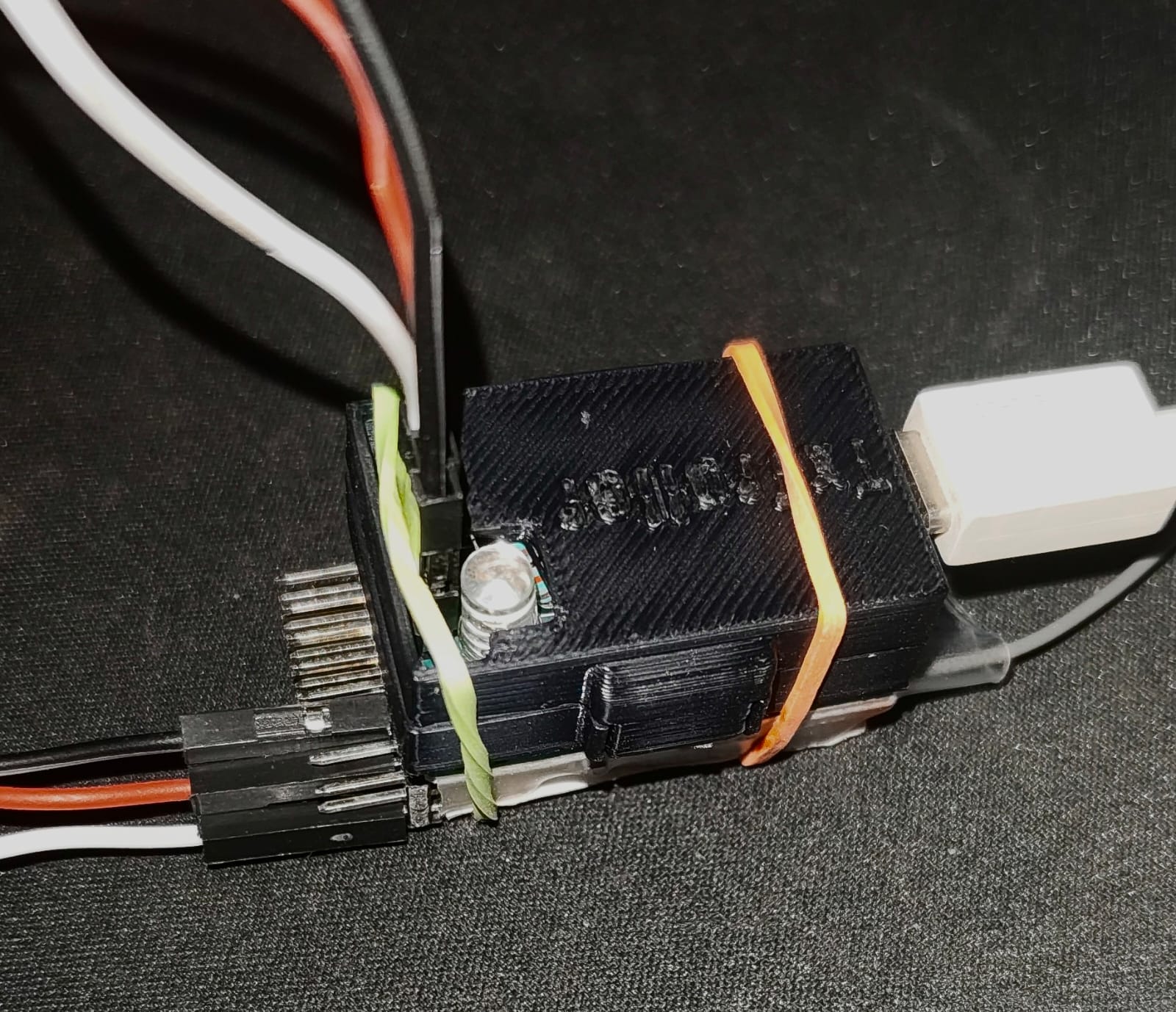
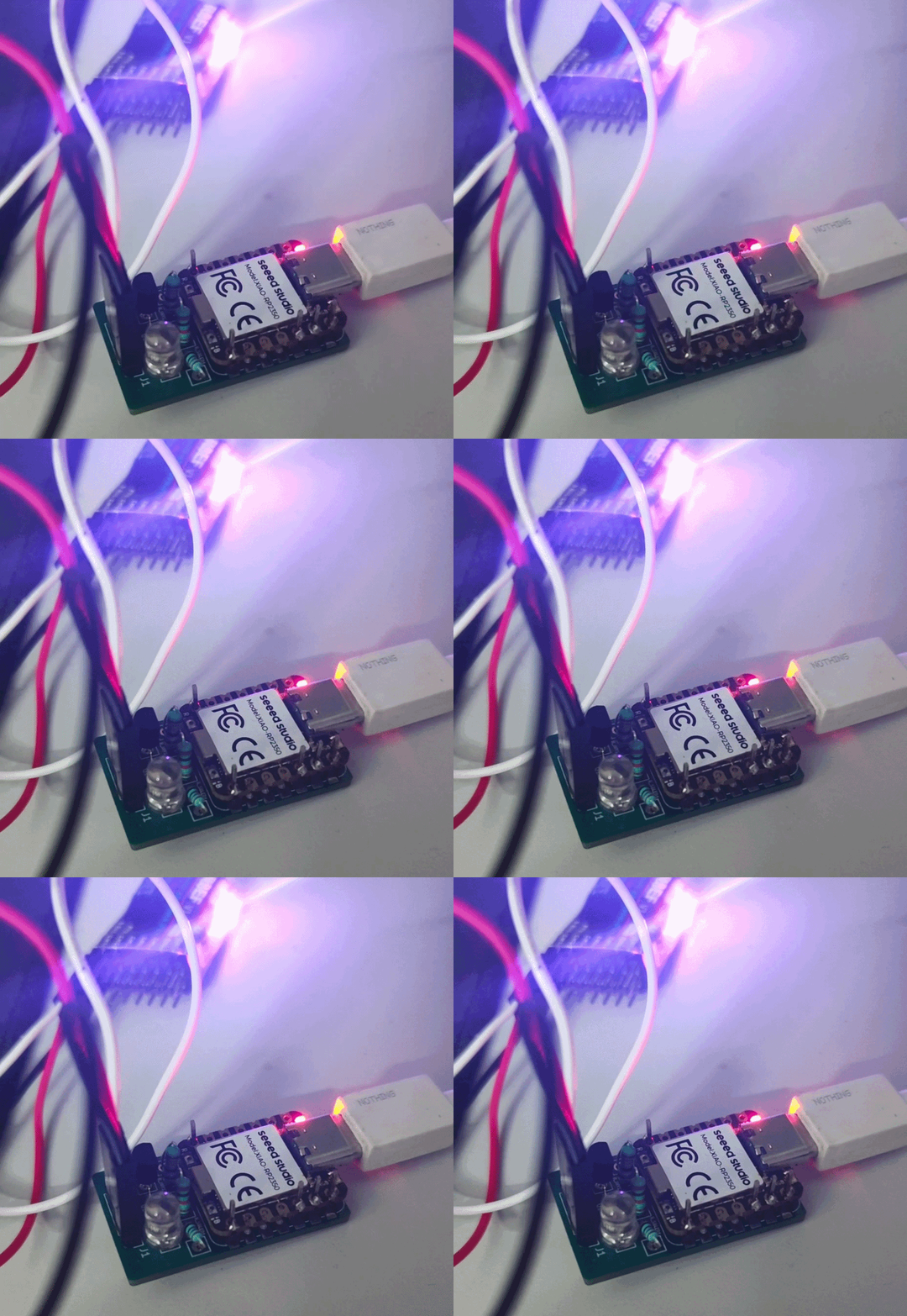
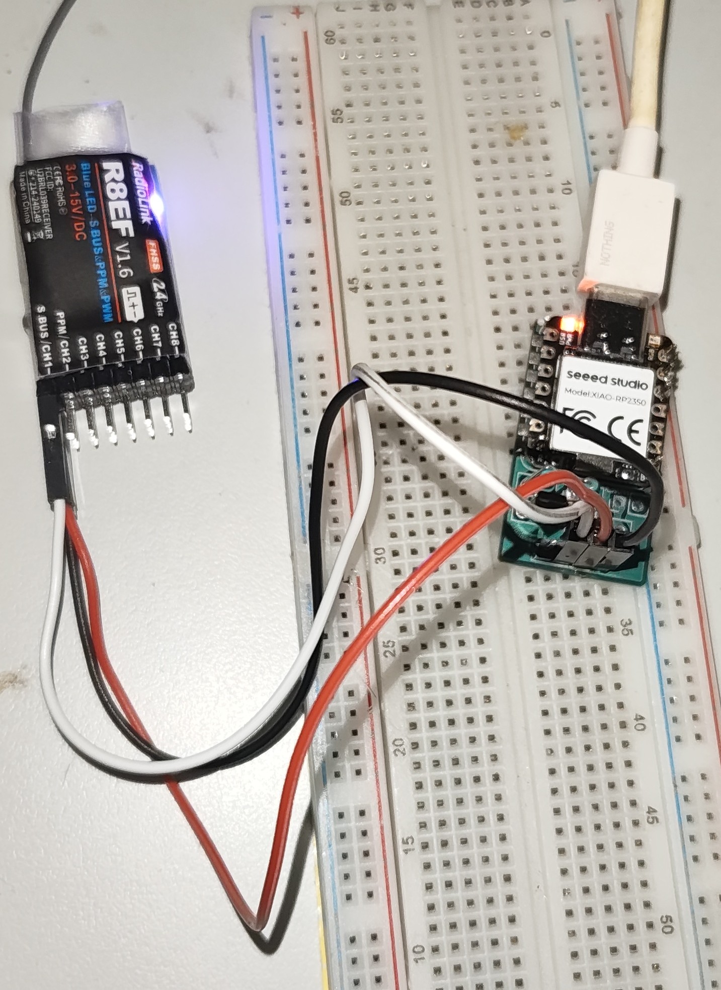
Click to open in YouTube

This is a simple adapter that will allow older-style Radio transmitter / receiver combos to be used as video-game controllers using the USB HID Gamepad device class.
Watch me crash quads using TxTroller: youtube video link
For the initial stages, this is being developed for the Radiolink R8EF receiver, which is an 8-channel receiver operating on the 2.4GHz frequency band.
As for the transmitter that will be the actual gamepad, It will be the Radiolink T8FB transmitter, which is a 2.4GHz 8 Channels RC Remote Transmitter.
The microcontroller that will be responsible for translating the SBUS signals from the receiver to the USB device class is the XIAO RP2040 due to it's small footprint and easy-to-use C/C++ SDK.
The PCB has been designed using KiCAD 9.0. It is a 2 layer PCB with both top and bottom having thick signal traces and a ground fill.
PCB Schematics:
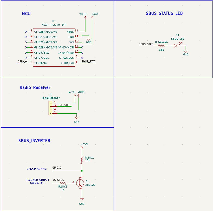
PCB layout:
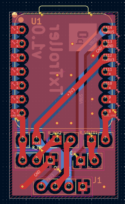
PCB Preview:
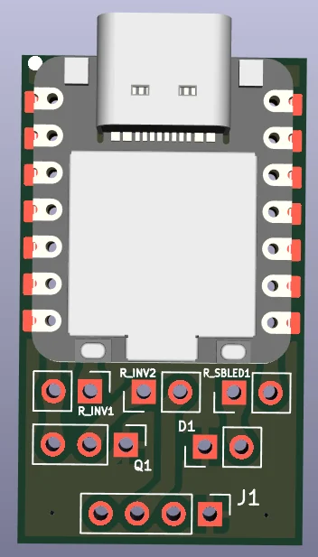
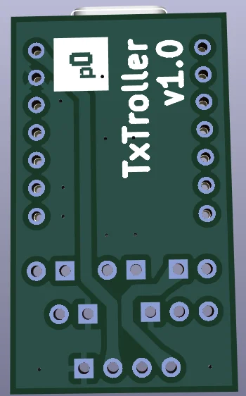
The case has been designed in Fusion 360, with the .f3z available in the /CAD directory, along with the exported .step files of the top and bottom parts of the case in /CAD/exports.
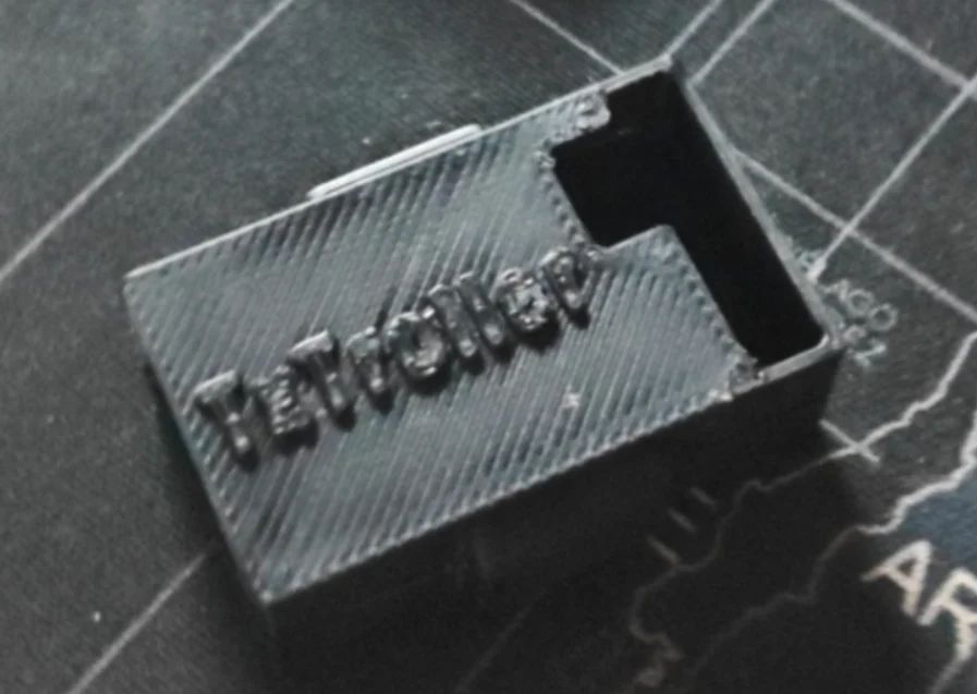
The case looks like this:
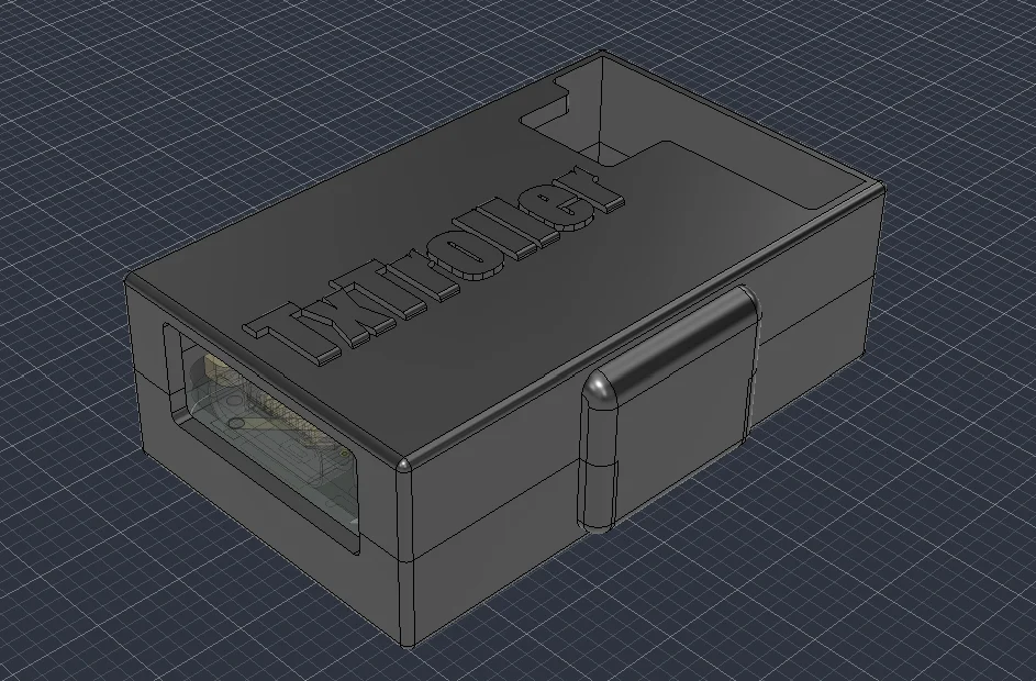
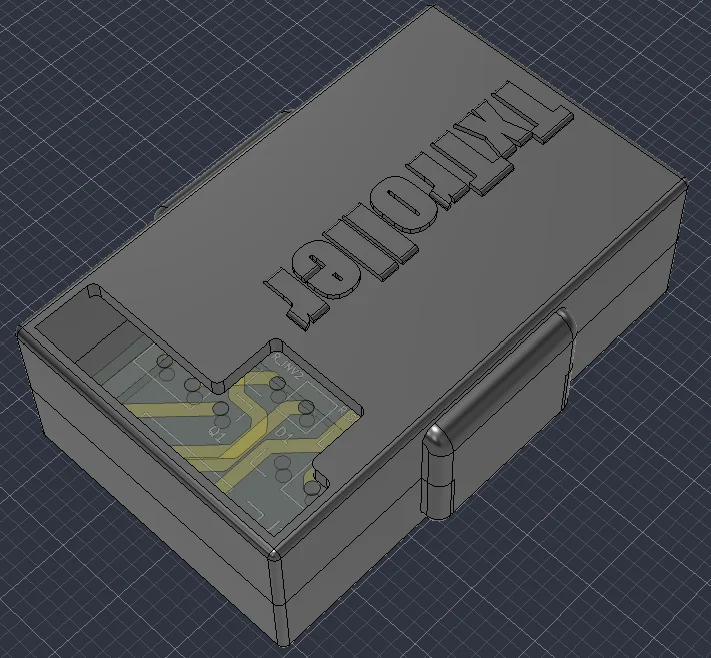
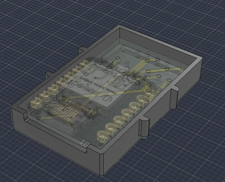
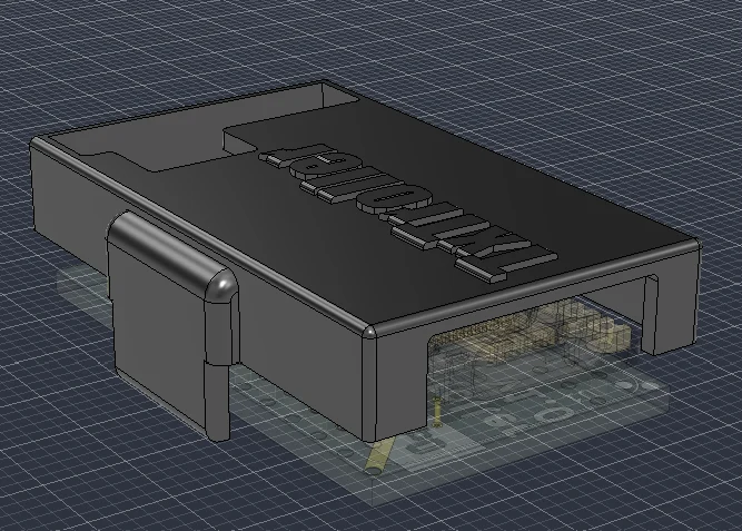
The case has side extrusions for friction-fitting the top and bottom part of the case together.
Originally modified from raspberrypi/pico-examples/tree/master/usb/device/dev_hid_composite .
Checkout the Firmware directory to view more information on button mappings, firmware compiling / flashing and testing the data received from the receiver.
The PCB contains no SMD components or any other component that cannot be soldered using a normal soldering iron, hence no PCBA is required.
The PCB gerber .zip file is available in PCB/exports/.
| S.No | Item Name | Description | Product URL | Qty | Unit Price ($) | Effective Price ($) |
|---|---|---|---|---|---|---|
| 1 | XIAO RP2040 | RP2040 Microcontroller | XIAO RP2040 | 1 | 6.14 | 6.14 |
| 2 | PCB | PCB manufacturing cost (5 qty) | Lion Circuits | 1 | 9.84 | 9.84 |
| 3 | 1k Ohm Resistor | 1k Ohm Resistor - Pack of 10 | 1k Resistor Pack | 1 | 0.13 | 0.13 |
| 4 | 10k Ohm Resistor | 10k Ohm Resistor - Pack of 10 | 10k Resistor Pack | 1 | 0.14 | 0.14 |
| 5 | 100 Ohm Resistor | 100 Ohm Resistor - Pack of 10 | 100 Ohm Resistor Pack | 1 | 0.16 | 0.16 |
| Total | 16.41$ |
Note that the PCB states 150ohm resistor but we have only added 100ohm, this is because we can arrange 3 100 ohm resistors in such a way that the effective resistance becomes 150ohms (2parallel+1series).
As for the 3d prints, the following files need to be printed separately:
Since they are designed to be friction fitted, no screws or heatset-inserts are needed.
| Qty | Value | Footprint | References |
|---|---|---|---|
| 1 | 10k | Connector_PinHeader_2.54mm:PinHeader_1x02_P2.54mm_Vertical | R_INV1 |
| 1 | 150 | Connector_PinHeader_2.54mm:PinHeader_1x02_P2.54mm_Vertical | R_SBLED1 |
| 1 | 1k | Connector_PinHeader_2.54mm:PinHeader_1x02_P2.54mm_Vertical | R_INV2 |
| 1 | 2N2222 | Connector_PinHeader_2.54mm:PinHeader_1x03_P2.54mm_Vertical | Q1 |
| 1 | LOGO | LOGO | G*** |
| 1 | RadioReceiver | Connector_PinHeader_2.54mm:PinHeader_1x04_P2.54mm_Vertical | J1 |
| 1 | SBUS_LED | Connector_PinHeader_2.54mm:PinHeader_1x02_P2.54mm_Vertical | D1 |
| 1 | XIAO-RP2040-DIP | Seeed Studio XIAO Series Library:XIAO-RP2040-DIP | U1 |
It measures 19.9 × 34 mm and has 2 copper layers, 1.6 mm thick.
8 parts. The full list of its parts is on this page, with links to each part's symbol and footprint where PCBKit's library has them.
From the Person-0/TxTroller repository on GitHub, at the commit this page was made from: the board is PCB/TxTroller.kicad_pcb and its schematic PCB/TxTroller.kicad_sch. PCBKit opens the board in the browser, with nothing to install.
Its repository publishes it under the MIT licence: you may reuse it on that licence's terms (keep the author's notice, and for a copyleft licence share your changes alike).

joeycastillo/Sensor-Watch
A board replacement for the classic Casio F-91W wristwatch

rusefi/rusefi
rusefi - GPL internal combustion engine control unit

hoglet67/RGBtoHDMI
Bare-metal Raspberry Pi project that provides pixel-perfect sampling of Retro Computer RGB/YUV video and conversion to HDMI

shanteacontrols/OpenDeck
A platform for building interactive control and sensing devices using MIDI and OSC built with Zephyr RTOS.

hackclub/OnBoard
💡 Join 1,000 teenagers and make your first PCB with a $100 grant!

dangiu/PicoMemcard
Emulating PSX Memory Card (or controller) using a Raspberry Pi Pico

OLIMEX/DIY-LAPTOP
Do It Yourself Open Source Hardware and Software Modular Hacker's Friendly Laptop