4 layers181.5 × 182.3 mm
Stencil
jerry-kerenzikov/ytterbium
Project files for Ytterbium modular CPU platform and Yprog programming tool
421 partsCERN-OHL-S-2.0

 perriestudios/SMD-Soldering-PCB1
A PCB I designed as a TA for EE 201 at UW over the Winter 2024
SmdPracticeBoard is an open-source printed circuit board by perriestudios, from the perriestudios/SMD-Soldering-PCB repository on GitHub. It is a 2-layer board of 91.4 × 73.7 mm with 34 parts on 23 nets, routed with 147 tracks and 22 vias.
It is built around the 74AHC1G08GW, 74AHC1G14GV and 74AHC1G32GW, with the 74AHC1G86SE and UJC-HP-3-SMT-TR among its other parts. Its parts include 6 resistors, 5 ICs, 3 diodes, 3 switches and 1 capacitor.


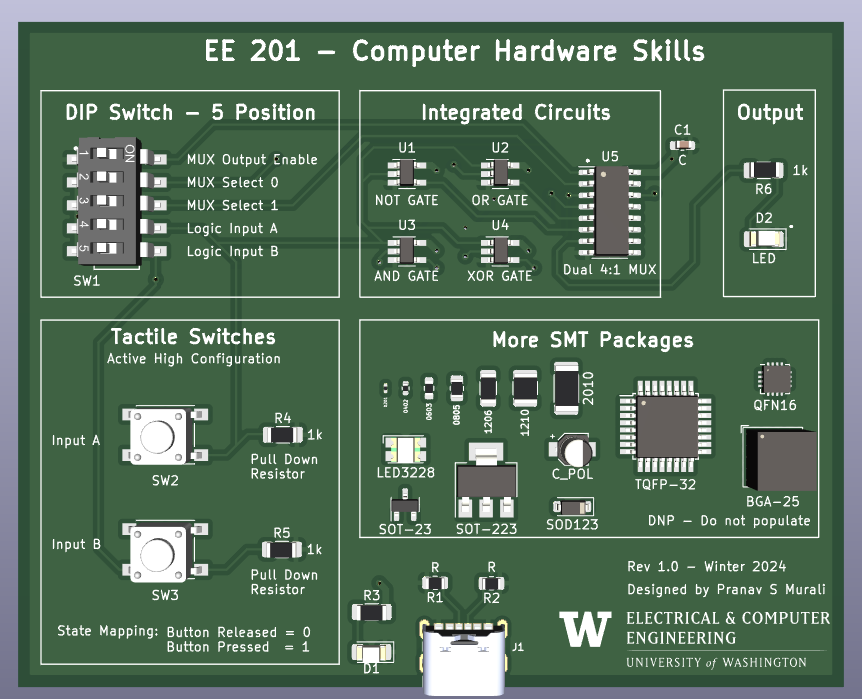
This PCB was designed with the goal of teaching students how to solder surface mount components.
The core logic of the circuit is the logic gates NOT, AND, OR and XOR. There is a multiplexer the outputs of one of these gates to the LED used for indication.
Power supply for the PCB is through a Type-C USB.
There are two tactile switches (push buttons), used to emulate the inputs A and B for the logic gates. The circuit is in active-high configuration with a weak pull-down resistor of 1k. This value was chosen to consolidate the BOM and limit the number of unique resistors(since LEDs also need current limiting resistors).
A DIP Switch is used to set the MUX configuration of Enable, S0 and S1. The other two inputs of the DIP switch can be used as a back up for inputs A and B.
This section is used to provide an overview of some commonly available SMD packages of Passives, Transistors and ICs. Students will not solder this, it is just to give them a feel of how big components are.
In the process of completing this design, there were several tradeoffs and decisions made. The biggest factor influencing the choices was a circuit of reasonable complexity for Sophomores to solder in approximately 1 hour.
This design was inspired by Educational Logic Gates PCB
| Qty | Value | Footprint | References |
|---|---|---|---|
| 4 | 1k | Resistor_SMD:R_1206_3216Metric_Pad1.30x1.75mm_HandSolder | R3, R4, R5, R6 |
| 2 | LED | LED_SMD:LED_1206_3216Metric_Pad1.42x1.75mm_HandSolder | D1, D2 |
| 2 | R | Resistor_SMD:R_0805_2012Metric | R1, R2 |
| 2 | SW_Push | Button_Switch_SMD:SW_Push_1P1T_NO_6x6mm_H9.5mm | SW2, SW3 |
| 1 | 0.1uF | Capacitor_SMD:C_0603_1608Metric_Pad1.08x0.95mm_HandSolder | C1 |
| 1 | 74153 | Package_SO:SOIC-16_3.9x9.9mm_P1.27mm | U5 |
| 1 | 74AHC1G08 | Package_TO_SOT_SMD:SOT-23-5_HandSoldering | U3 |
| 1 | 74AHC1G14 | Package_TO_SOT_SMD:SOT-23-5_HandSoldering | U1 |
| 1 | 74AHC1G32 | Package_TO_SOT_SMD:SOT-23-5_HandSoldering | U2 |
| 1 | 74AHC1G86 | Package_TO_SOT_SMD:SOT-23-5_HandSoldering | U4 |
| 1 | BGA-25_6.35x6.35mm_Layout5x5_P1.27mm | Package_BGA:BGA-25_6.35x6.35mm_Layout5x5_P1.27mm | BGA-25 |
| 1 | CP_Elec_3x5.3 | Capacitor_SMD:CP_Elec_3x5.3 | C_POL |
| 1 | D_SOD-123 | Diode_SMD:D_SOD-123 | SOD123 |
| 1 | LED_Avago_PLCC4_3.2x2.8mm_CW | LED_SMD:LED_Avago_PLCC4_3.2x2.8mm_CW | LED3228 |
| 1 | LOGO | LOGO | G*** |
| 1 | QFN-16-1EP_3x3mm_P0.5mm_EP1.9x1.9mm | Package_DFN_QFN:QFN-16-1EP_3x3mm_P0.5mm_EP1.9x1.9mm | QFN16 |
| 1 | R_0201_0603Metric | Resistor_SMD:R_0201_0603Metric | 0201 |
| 1 | R_0402_1005Metric | Resistor_SMD:R_0402_1005Metric | 0402 |
| 1 | R_0603_1608Metric | Resistor_SMD:R_0603_1608Metric | 0603 |
| 1 | R_0805_2012Metric | Resistor_SMD:R_0805_2012Metric | 0805 |
| 1 | R_1206_3216Metric | Resistor_SMD:R_1206_3216Metric | 1206 |
| 1 | R_1210_3225Metric | Resistor_SMD:R_1210_3225Metric | 1210 |
| 1 | R_2010_5025Metric | Resistor_SMD:R_2010_5025Metric | 2010 |
| 1 | SW_DIP_x05 | CTS-219-5MST:CTS-219-5MST-0 | SW1 |
| 1 | TQFP-32_7x7mm_P0.8mm | Package_QFP:TQFP-32_7x7mm_P0.8mm | TQFP-32 |
| 1 | UJC-HP-3-SMT-TR | UJC-HP-3-SMT-TR:CUI_UJC-HP-3-SMT-TR | J1 |
The 32 most common of 34 parts.
jerry-kerenzikov/ytterbium
Project files for Ytterbium modular CPU platform and Yprog programming tool

roberto314/Unicomp2
A modular 8-bit Computer able to recreate (nearly) every Retro computer of the late 70s to mid 80s.

gadjet/Window-Door-sensor-Version-5
Version 5 of the Window/Door sensor project this time with ultra low current consumption

starlingcode/analog-via
Designs for an all-analog variant of the VIA meta crossfader


elixpo/elixpo_chapter
Elixpo’s canonical collection for public build-and-release Chapters, bringing open-source software, reproducible research, hardware, and community contributions into one attributable record.


It measures 91.4 × 73.7 mm and has 2 copper layers, 1.6 mm thick.
34 parts, built around the 74AHC1G08GW, 74AHC1G14GV, 74AHC1G32GW and 74AHC1G86SE. The full list of its parts is on this page, with links to each part's symbol and footprint where PCBKit's library has them.
From the perriestudios/SMD-Soldering-PCB repository on GitHub, at the commit this page was made from: the board is smdPracticeBoard.kicad_pcb and its schematic smdPracticeBoard.kicad_sch. PCBKit opens the board in the browser, with nothing to install.
Its repository states no licence, so its author keeps all rights: ask perriestudios before reusing the design.