


2 layers119.5 × 177 mm
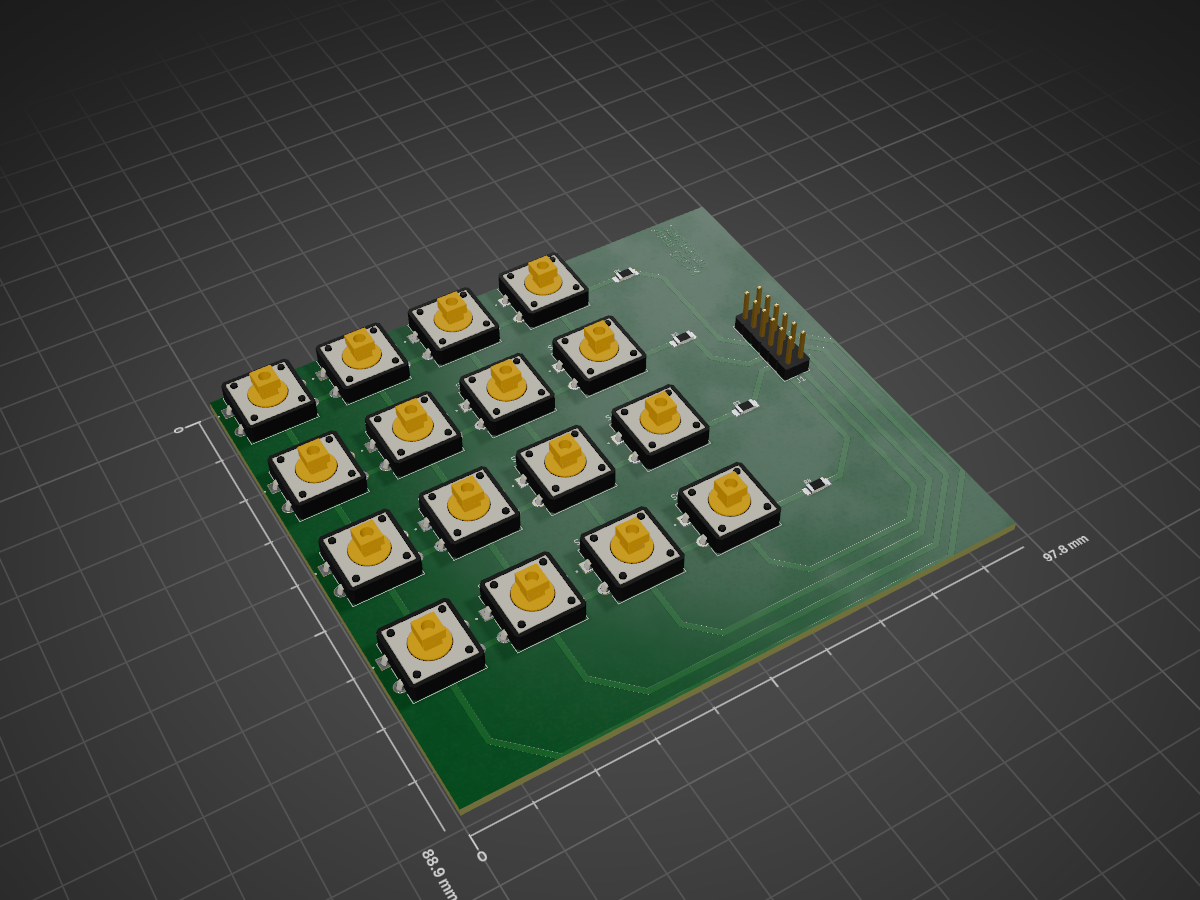
ESP32 (C) ile Basys3 FPGA (Verilog) için 4x4 Keypad ve KiCad PCB tasarım dosyalarını içerir.
Keypad is an open-source printed circuit board by peginium, from the peginium/Digital_Design-Bonus_Project repository on GitHub. It is a 2-layer board with 21 parts on 16 nets, routed with 77 tracks and 0 vias.
It is built around the TL3301AF160QG. Its parts include 16 switches, 4 resistors and 1 connector. It belongs with the keyboards and input boards of this library.



Bu repo, ESP32 ve FPGA üzerinde gerçekleştirilmiş bir 4x4 Matris Keypad tasarımını ve uygulamasını içerir. Ayrıca KiCad ile tasarlanmış özel bir PCB tasarımını da içermektedir.
├── 📁 keypad_fpga/         # Basys3 için Verilog tasarımı
│   ├── keypad.v        # Verilog kaynak kodu
│   └── Basys-3-Master.xdc     # Basys3 için pin planlaması
├── 📁 keypad_mcu/       # ESP32 için C kodları
│   ├── keypad.ino
├── 📁 kicad_design/         # PCB tasarım Dosyaları
│   ├── keypad.kicad_sch  # Şematik Dosyası
│   └── keypad.kicad_pcb  # PCB layout
└── README.md| Qty | Value | Footprint | References |
|---|---|---|---|
| 16 | TL3301AF160QG | TL1100F160Q-kicad_modv6:TL1100F160Q | S1, S2, S3, S4, S5, S6, S7, S8, S9, S10, S11, S12, S13, S14, S15, S16 |
| 4 | ERA8ARW6042V | ERA8ARW6042V-kicad_modv6:RES_ERA8ARW6042V | R1, R2, R3, R4 |
| 1 | Conn_02x06_Odd_Even | Connector_PinHeader_2.54mm:PinHeader_2x06_P2.54mm_Vertical | J1 |

kulovac/tuner-pedal
Source for my tuner pedal project from algorithm design to PCB implementation


gusmanb/logicanalyzer
24 channel, 100Msps logic analyzer hardware and software

mntmn/amiga2000-gfxcard
MNT VA2000, an Open Source Amiga 2/3/4000 Graphics Card (Zorro II/III), written in Verilog

21 parts, built around the TL3301AF160QG. The full list of its parts is on this page, with links to each part's symbol and footprint where PCBKit's library has them.
From the peginium/Digital_Design-Bonus_Project repository on GitHub, at the commit this page was made from: the board is kicad_design/keypad.kicad_pcb and its schematic kicad_design/keypad.kicad_sch. PCBKit opens the board in the browser, with nothing to install.
Its repository states no licence, so its author keeps all rights: ask peginium before reusing the design.