Skip to the content
2 layers95 × 95 mmTripel, the printed circuit board in 3D

Ortholinear 60% 3-part keyboard PCB

Size
95 × 95 mm
Copper layers
2
Thickness
1.6 mm
Parts
90
Nets
53
Pads
354
Tracks, vias
694, 19
Pours
2
Routed
Yes
KiCad
KiCad 5 (file 20171130)
Created
14 Sep 2019
Updated
18 Sep 2020

Overview

Tripel is an open-source printed circuit board by peej, from the peej/tripel-keyboard repository on GitHub. It is a 2-layer board of 95 × 95 mm with 90 parts on 53 nets, routed with 694 tracks and 19 vias.

Its parts include 41 switches, 24 diodes, 13 connectors and 1 IC. It belongs with the keyboards and input boards and the AVR (ATmega, ATtiny) boards of this library.

README

README.md

Tripel - Ortholinear 60% keyboard PCB

Tripel is a 15 column ortholinear keyboard PCB.

The goal of this project is to build an all throughhole component, pro-micro powered ortholinear PCB that fits in a standard 60% tray mount case but built from sub-100x100mm PCB boards.

Inspired by the modular PCB projects of 40Percent.club like the Nori.
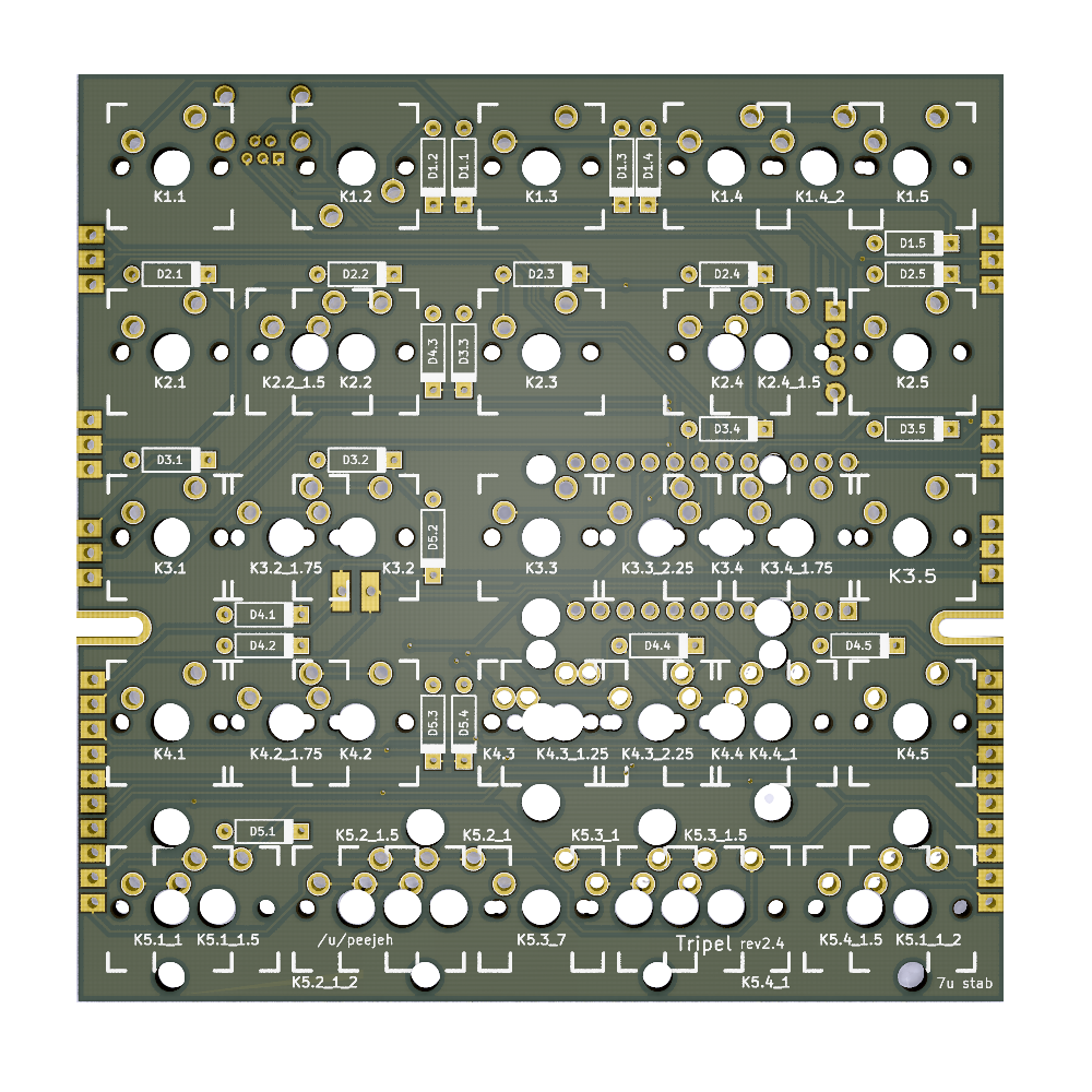
PCB render

  • Designed to be easy to build with minimal soldering experience.
  • Built from 3 of the same PCB.
  • 7u spacebar bottom row.

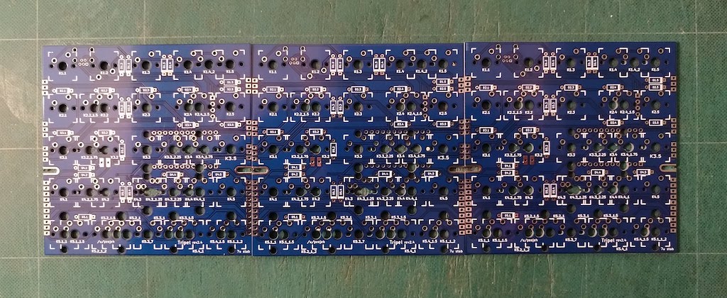
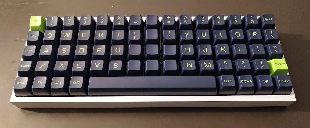
Layout options PCBs layed out Built keyboard

Bill of Materials (BOM)

  • 3 PCBs.
  • A suitable 60% ortholinear keyboard plate (eg. XD75 plate).
  • 65 MX compatible switches.
  • 65 1n4148 diodes.
  • Pro Micro controller (or compatible alternative).
  • 7u PCB mount stabilizer.
  • Through-hole USB mini or micro connector.
  • USB cable for Pro Micro.

Ordering PCBs

PCBs can be manufactuered by a variety of online PCB fabricators. You can use PCBShopper to search for the best price. Many manufacturers have special rates for prototype boards under 100x100mm in size.
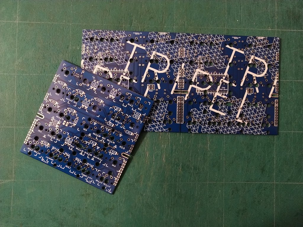
PCBs

The zip file in the gerber directory contains the gerber files your fabricator will need to make the PCB tripel.zip PCB.

When uploading the gerber zip files, use the default PCB settings.
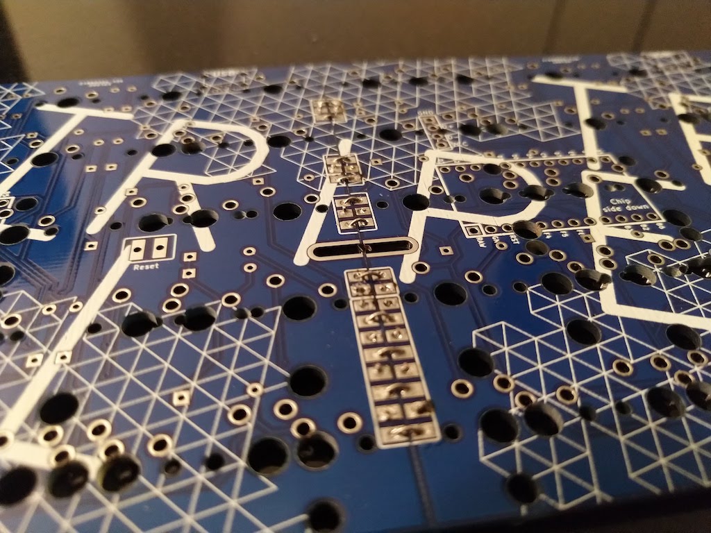
Construction

  • You will need 3 PCBs.
  • Solder the diodes onto each PCB.
    • You can place them on either side, but the drawing on the soldermask is on the front of the PCB.
    • The diodes under the Pro Micro must go on the front side of the PCB.
    • The end of the diode with black band goes in the square hole.
  • Solder on the Pro Micro headers onto the underside of one PCB.
    • Do not solder on the Pro Micro yet.
    • You can place the Pro Micro on any of the 3 PCBs, pick the placement that works best for your case.
    • To get keep the headers straight while soldering, place the Pro Micro over the headers to hold them in place.
    • If you want to use a socket for your Pro Micro, solder on a socket instead.
  • Solder on the USB connector to the underside of the left PCB.
  • Insert the switches into the plate.
    • If using a XD75 ortholinear plate, you will need to modify it if you are using an incompatible layout.
  • Join the PCBs together by solder the solder bridges between the PCBs.
    • Solder all pad bridges between the 3 PCBs.
    • Use small bent pieces of trimmed diode wire to bridge the solder bridges instead of just using solder.
  • Put the 7u stabilizer together and fit it into the left and right PCBs.
    • If you are using the standard modifier keycap sizes, you will also want to add 2u stabs for those keys.
    • If you forget the stabilizer you will need to unsolder all of the switches so as to fit it.
    • Don't forget to trim and lube your stabilizer before fitting if you want to.
  • Place the PCBs onto the switches:
    • Insert all the switches and ensure that the pins of each switch are correctly coming through the board and are not bent under the PCB.
  • Solder all the switch pins.
    • Some switches might foul on your case mounting posts stopping the PCB from sitting flush, before soldering, trim the switch pins which would foul so they are flush with the PCB.
    • The switch next to the Pro Micro might need to have it's pins trimmed so that your USB cable can plug in and sit as flush as possible to the PCB.
  • Solder on the Pro Micro:
    • Ensure that you have it the correct way around, the chip side should be face down towards the PCB with the USB port to the right.
    • You might want to plug in your USB cable while soldering so that the Pro Micro is mounted far enough from the PCB for the cable to plug in successfully.
    • Use electrical tape underneath the Pro Micro if you think shorting against the switch pins could be an issue.
  • Cut your USB cable to length and solder the wires to the pads for the USB connector.
  • Wire colours may vary, but usually: Red = VCC; black = GND; white = D-; green = D+

Connecting the PCBs together

Firmware

Build and flash the Pro Micro with QMK firmware, see the QMK documentation on how to do this.

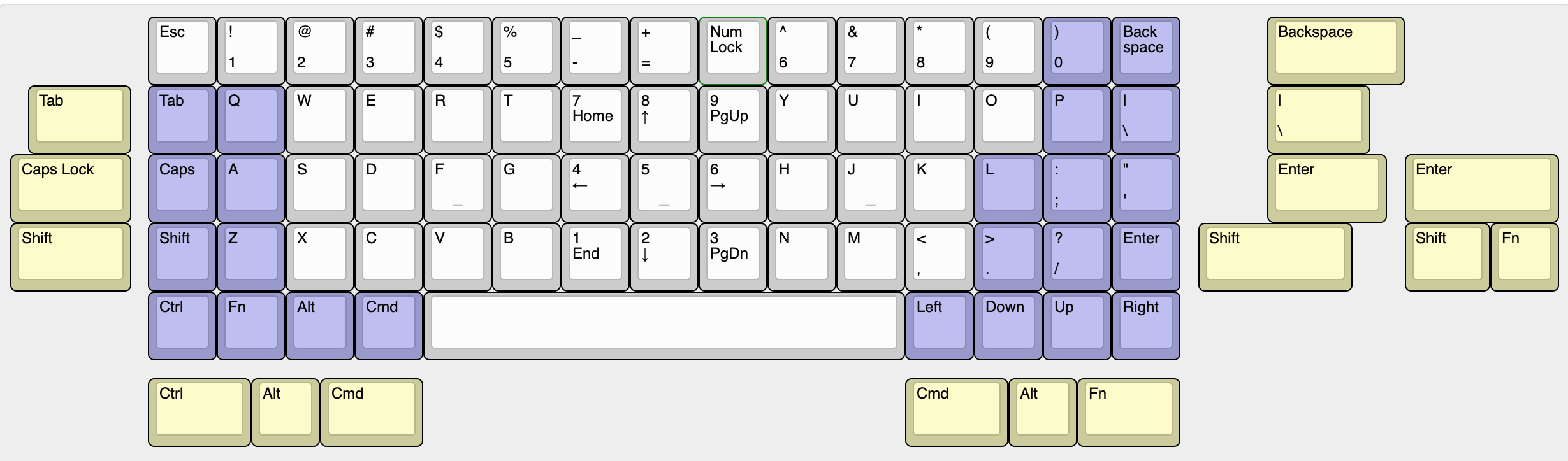
The required pinout for the firmware is shown in this KLE layout:
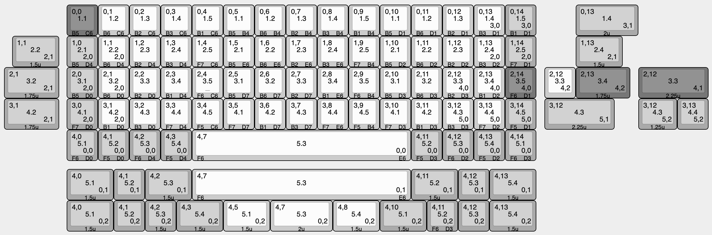
PCB render

A preconfigured firmware is not yet available in the QMK repo but can be found here in my fork.

Differences to the XD75

The main difference to the XD75 is the alternative layout options.

  • Supports PCB mount stabilizers for a 7u (or 2u) "spacebar"
  • Supports PCB mount stabilizers for non-1u layout, 2u "backspace", 2.75u "enter" and "right shift" keys.
  • The Tripel does not support the full-grid layout of the XD75 as there are not enough pins on the Pro Micro

Parts

90
QtyValueFootprintReferences
27KEYSWkeyboard:MXK1.1, K1.2, K1.3, K1.4, K1.5, K2.1, K2.2, K2.3, K2.4, K2.5, K3.1, K3.2, K3.3, K3.4, K3.5, K4.1 +11
24Dkeyboard:DIODED1.1, D1.2, D1.3, D1.4, D1.5, D2.1, D2.2, D2.3, D2.4, D2.5, D3.1, D3.2, D3.3, D3.4, D3.5, D4.1 +8
6KEYSWkeyboard:MX_PCB_150HK2.2_1.5, K2.4_1.5, K5.1_1.5, K5.2_1.5, K5.3_1.5, K5.4_1.5
3KEYSWkeyboard:MX_PCB_175HK3.2_1.75, K3.4_1.75, K4.2_1.75
2Far Left Rowskeyboard:CONNECTOR_3J12, J13
2KEYSWkeyboard:MX_PCB_225HK3.3_2.25, K4.3_2.25
2KEYSWkeyboard:MX_PCB_200HK1.4_2, K5.3_7
2Left Rowskeyboard:CONNECTOR_3J2, J5
2Right Rowskeyboard:CONNECTOR_3J3, J8
1Conn_01x04keyboard:CONNECTOR_4J7
1KEYSWkeyboard:MX_PCB_125HK4.3_1.25
1Left Columnskeyboard:CONNECTOR_8J1
1Left Resetkeyboard:CONNECTOR_2J11
1ProMicro_ChipSideDownkeyboard:Pro_Micro_ChipSideDownU1
1Resetkeyboard:RESETJ9
1Right Columnskeyboard:CONNECTOR_8J4
1Right Resetkeyboard:CONNECTOR_2J10
1USB_mini_micro_Bkeyboard:USB_Mini-BJ6

The 79 most common of 90 parts.

Similar boards

  • 2 layers75 × 75 mmFtp, the printed circuit board in 3D

    Ftp

    opulo-inc/lumenpnp

    The LumenPnP is an open source pick and place machine.

    90 parts3.7k
  • 2 layers236.5 × 96.2 mmForager pcb, the printed circuit board in 3D

    Forager pcb

    carrefinho/forager

    34-key wireless split keyboard inspired by ZSA Voyager

    90 parts426CERN-OHL-P-2.0
  • 2 layers268 × 62 mmSmu front 1, the printed circuit board in 3D

    Smu front 1

    jaromir-sukuba/J-SMU

    DIY source-measure unit

    90 parts244
  • 2 layers97.5 × 59.5 mmChrono, the printed circuit board in 3D

    Chrono

    eddyem/stm32samples

    Code samples and ready projects based on bare-metal STM32

    90 parts208
  • 2 layers115.6 × 106.7 mmErgoSNM v3 left, the printed circuit board in 3D

    ErgoSNM v3 left

    siderakb/ergo-snm-keyboard

    ErgoSNM is a split ergonomic keyboard integrated with trackball, wireless is in beta

    90 parts172CERN-OHL-P-2.0
  • 2 layers163 × 120 mmZynthian mini, the printed circuit board in 3D

    Zynthian mini

    zynthian/zynthian-hw

    Zynthian hardware stuff: PCBs, schemes, parts specifications, pin assignment, ...

    90 parts156
  • 2 layers219 × 96.1 mmTheENDGAME2024 COPPER, the printed circuit board in 3D

    TheENDGAME2024 COPPER

    OldMan6955/TheEndgame2024

    Love Peace UWU

    90 parts121CERN-OHL-S-2.0

Questions

How big is the Tripel PCB?

It measures 95 × 95 mm and has 2 copper layers, 1.6 mm thick.

What parts does the Tripel use?

90 parts. The full list of its parts is on this page, with links to each part's symbol and footprint where PCBKit's library has them.

Where can I download the Tripel KiCad files?

From the peej/tripel-keyboard repository on GitHub, at the commit this page was made from: the board is tripel.kicad_pcb. PCBKit opens the board in the browser, with nothing to install.

Can I use the Tripel design in my own project?

Its repository states no licence, so its author keeps all rights: ask peej before reusing the design.