
2 layers285.4 × 94.9 mm
Rosaline
peej/rosaline-keyboard
40% staggered through-hole component keyboard PCB for standard 60% cases
148 parts53MIT

 peej/rosaline-keyboard53
40% staggered through-hole component keyboard PCB for standard 60% cases
Rosaline ortho is an open-source printed circuit board by peej, from the peej/rosaline-keyboard repository on GitHub, published under the MIT licence. It is a 2-layer board of 285.4 × 94.9 mm with 155 parts on 92 nets, routed with 892 tracks and 38 vias.
It is built around the ATMEGA328-PU. Its parts include 64 diodes, 8 resistors, 5 capacitors, 3 connectors and 2 switches. It belongs with the keyboards and input boards and the AVR (ATmega, ATtiny) boards of this library.
Rosaline is a 40% keyboard PCB using through-hole components for that visible component aesthetic.
The goal of this project is to build an all through-hole component 40% PCB that fits in a standard 60% tray mount case.
Inspired by the Plaid and the Romeo.
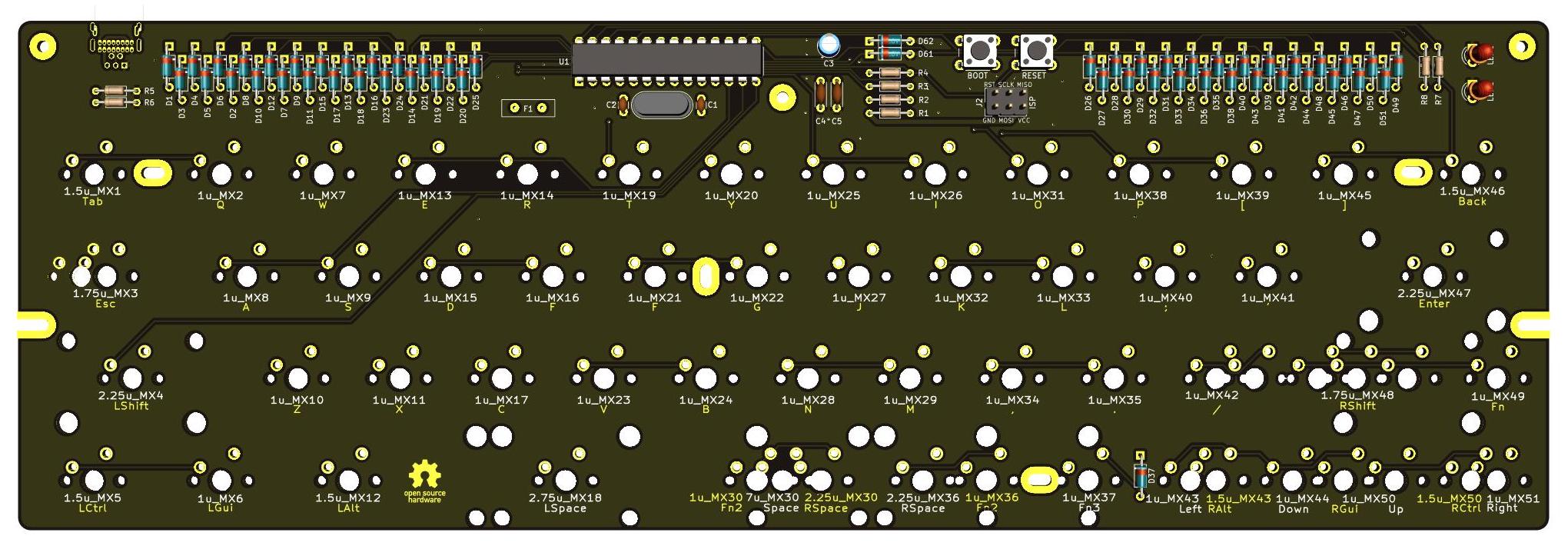
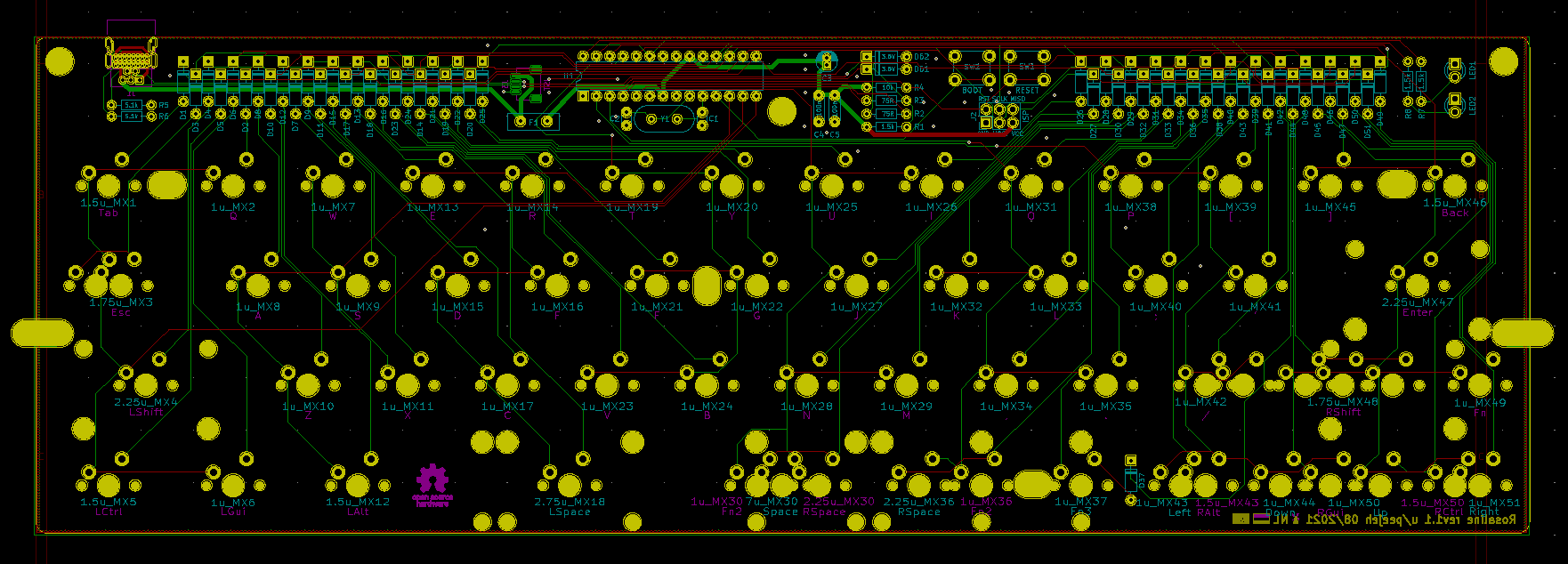
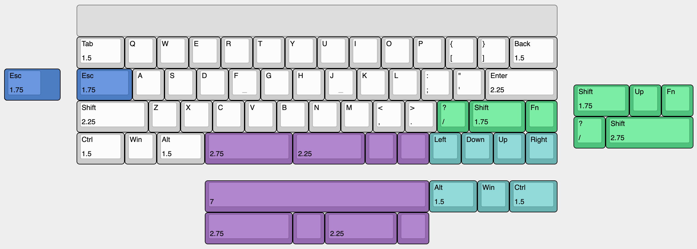
The layout is a number row-less 60% layout with split spacebar or 7u bottom row and split right shift. An arrow cluster layout is also supported by moving the right shift.
PCBs can be manufactuered by a variety of online PCB fabricators. You can use PCBShopper to search for the best price.
Solder all the components onto the top side of the PCB except the USB connector which should be on the back of the board. Leave the larger components until last so that the board will lie flat upsidedown while you solder the resistors and capacitors.
Take care to put the correct value resistors and capacitors in the correct places, the values are written on the silkmask along with the component reference. If you are unsure about the value of a resistor, check it with a multimeter.
Ensure that polarised components (diodes, LEDs, electrolytic capacitor (C3), IC socket) are in the correct orientation. The square pad is for the negative side of the component; for a diode this means the side with the black stripe; for LEDs and C3 the short leg is the cathode and goes in the square pad.
Firmware has not been merged into QMK upstream as of yet.
If you are building your own firmware, the following matrix information will be useful to you:
| Configuration | Value |
|---|---|
| MATRIX_ROWS | 7 |
| MATRIX_COLS | 8 |
| MATRIX_ROW_PINS | C0, B5, B4, B3, B2, B1, C3 |
| MATRIX_COL_PINS | B0, D7, D6, C2, D4, D1, D0, C1 |
| DIODE_DIRECTION | COL2ROW |
Cut a piece of 2mm thick acrylic to size (285x19mm) and drill 3 m2 holes for the standoffs. Use the PCB as a guide for the hole positions.
Affix the 3 standoffs to the PCB with screws from underneath the PCB. Use the remaining 3 screws to attach the acrylic to the top of the standoffs.
| Qty | Value | Footprint | References |
|---|---|---|---|
| 60 | 1N4148 | Diode_THT:D_DO-35_SOD27_P7.62mm_Horizontal | D1, D2, D10, D11, D12, D13, D14, D15, D16, D17, D18, D19, D20, D21, D22, D23 +44 |
| 3 | 1.5k | Resistor_THT:R_Axial_DIN0204_L3.6mm_D1.6mm_P7.62mm_Horizontal | R1, R7, R8 |
| 3 | M2 | juliet:MountingHole_M2 | H1, H4, H7 |
| 2 | . | juliet:MX | 1u_MX36, 1u_MX51 |
| 2 | 100n | Capacitor_THT:C_Disc_D4.3mm_W1.9mm_P5.00mm | C4, C5 |
| 2 | 22p | Capacitor_THT:C_Disc_D3.0mm_W1.6mm_P2.50mm | C1, C2 |
| 2 | 3.6V | Diode_THT:D_DO-35_SOD27_P7.62mm_Horizontal | D61, D62 |
| 2 | 5.1k | Resistor_THT:R_Axial_DIN0204_L3.6mm_D1.6mm_P7.62mm_Horizontal | R5, R6 |
| 2 | 75R | Resistor_THT:R_Axial_DIN0204_L3.6mm_D1.6mm_P7.62mm_Horizontal | R2, R3 |
| 2 | M2 | juliet:MountingSlot_M2 | H2, H9 |
| 1 | ' | juliet:MX | 1u_MX58 |
| 1 | , | juliet:MX | 1u_MX47 |
| 1 | / | juliet:MX | 1u_MX55 |
| 1 | 0 | juliet:MX | 1u_MX28 |
| 1 | 00 | juliet:MX | 1u_MX32 |
| 1 | 1 | juliet:MX | 1u_MX25 |
| 1 | 100mA | Fuse:Fuse_Bourns_MF-RHT100 | F1 |
| 1 | 10k | Resistor_THT:R_Axial_DIN0204_L3.6mm_D1.6mm_P7.62mm_Horizontal | R4 |
| 1 | 16MHz | Crystal:Crystal_HC49-4H_Vertical | Y1 |
| 1 | 2 | juliet:MX | 1u_MX29 |
| 1 | 3 | juliet:MX | 1u_MX33 |
| 1 | 4 | juliet:MX | 1u_MX26 |
| 1 | 4.7u | Capacitor_THT:CP_Radial_D4.0mm_P1.50mm | C3 |
| 1 | 5 | juliet:MX | 1u_MX30 |
| 1 | 6 | juliet:MX | 1u_MX34 |
| 1 | 7 | juliet:MX | 1u_MX27 |
| 1 | 8 | juliet:MX | 1u_MX31 |
| 1 | 9 | juliet:MX | 1u_MX35 |
| 1 | ; | juliet:MX | 1u_MX54 |
| 1 | A | juliet:MX | 1u_MX6 |
| 1 | ATMEGA328-PU | Package_DIP:DIP-28_W7.62mm | U1 |
| 1 | AVR_ISP_6 | Connector_PinHeader_2.54mm:PinHeader_2x03_P2.54mm_Vertical | J2 |
| 1 | B | juliet:MX | 1u_MX23 |
| 1 | BOOT | Button_Switch_THT:SW_PUSH_6mm | SW2 |
| 1 | Back | juliet:MX | 1u_MX57 |
| 1 | C | juliet:MX | 1u_MX15 |
| 1 | D | juliet:MX | 1u_MX14 |
| 1 | Down | juliet:MX | 1u_MX52 |
| 1 | E | juliet:MX | 1u_MX13 |
| 1 | Enter | juliet:MX | 1u_MX59 |
| 1 | Esc | juliet:MX | 1u_MX2 |
| 1 | F | juliet:MX | 1u_MX18 |
| 1 | Fn | juliet:MX | 1u_MX8 |
| 1 | G | juliet:MX | 1u_MX22 |
| 1 | GREEN | LED_THT:LED_D3.0mm | LED1 |
| 1 | H | juliet:MX | 1u_MX38 |
| 1 | I | juliet:MX | 1u_MX45 |
| 1 | J | juliet:MX | 1u_MX42 |
| 1 | JST | Connector_JST:JST_SH_SM04B-SRSS-TB_1x04-1MP_P1.00mm_Horizontal | J3 |
| 1 | K | juliet:MX | 1u_MX46 |
| 1 | L | juliet:MX | 1u_MX50 |
| 1 | LAlt | juliet:MX | 1u_MX12 |
| 1 | LCtrl | juliet:MX | 1u_MX4 |
| 1 | LGui | juliet:MX | 1u_MX16 |
| 1 | LShift | juliet:MX | 1u_MX3 |
| 1 | LSpace | juliet:MX | 1u_MX24 |
| 1 | LSpace | juliet:MX_PCB_200B | 2u_MX20 |
| 1 | Left | juliet:MX | 1u_MX48 |
| 1 | Lower | juliet:MX | 1u_MX20 |
| 1 | M | juliet:MX | 1u_MX43 |
| 1 | N | juliet:MX | 1u_MX39 |
| 1 | O | juliet:MX | 1u_MX49 |
| 1 | P | juliet:MX | 1u_MX53 |
| 1 | Q | juliet:MX | 1u_MX5 |
| 1 | R | juliet:MX | 1u_MX17 |
| 1 | RED | LED_THT:LED_D3.0mm | LED2 |
| 1 | RESET | Button_Switch_THT:SW_PUSH_6mm | SW1 |
| 1 | RSpace | juliet:MX_PCB_200B | 2u_MX44 |
| 1 | RSpace | juliet:MX | 1u_MX40 |
| 1 | Raise | juliet:MX | 1u_MX44 |
| 1 | Right | juliet:MX | 1u_MX60 |
| 1 | S | juliet:MX | 1u_MX10 |
| 1 | Space | juliet:MX_PCB_700H | 7u_MX32 |
| 1 | T | juliet:MX | 1u_MX21 |
| 1 | Tab | juliet:MX | 1u_MX1 |
| 1 | U | juliet:MX | 1u_MX41 |
| 1 | USB | juliet:USB_Hybrid_THT | J1 |
| 1 | Up | juliet:MX | 1u_MX56 |
| 1 | V | juliet:MX | 1u_MX19 |
| 1 | W | juliet:MX | 1u_MX9 |
The 150 most common of 155 parts.
peej/rosaline-keyboard
40% staggered through-hole component keyboard PCB for standard 60% cases


peej/lumberjack-keyboard
5x12 ortholinear through-hole component keyboard PCB for standard 60% cases

peterheinrich/InternetOverSpaghetti
Transmitting IP packages over a pair of spaghetti thus demonstrating how media independent IP really is.


It measures 285.4 × 94.9 mm and has 2 copper layers, 1.6 mm thick.
155 parts, built around the ATMEGA328-PU. The full list of its parts is on this page, with links to each part's symbol and footprint where PCBKit's library has them.
From the peej/rosaline-keyboard repository on GitHub, at the commit this page was made from: the board is rosaline-ortho.kicad_pcb. PCBKit opens the board in the browser, with nothing to install.
Its repository publishes it under the MIT licence: you may reuse it on that licence's terms (keep the author's notice, and for a copyleft licence share your changes alike).